Chassis Installation and Grounding
Installation Factors
Installation Factors
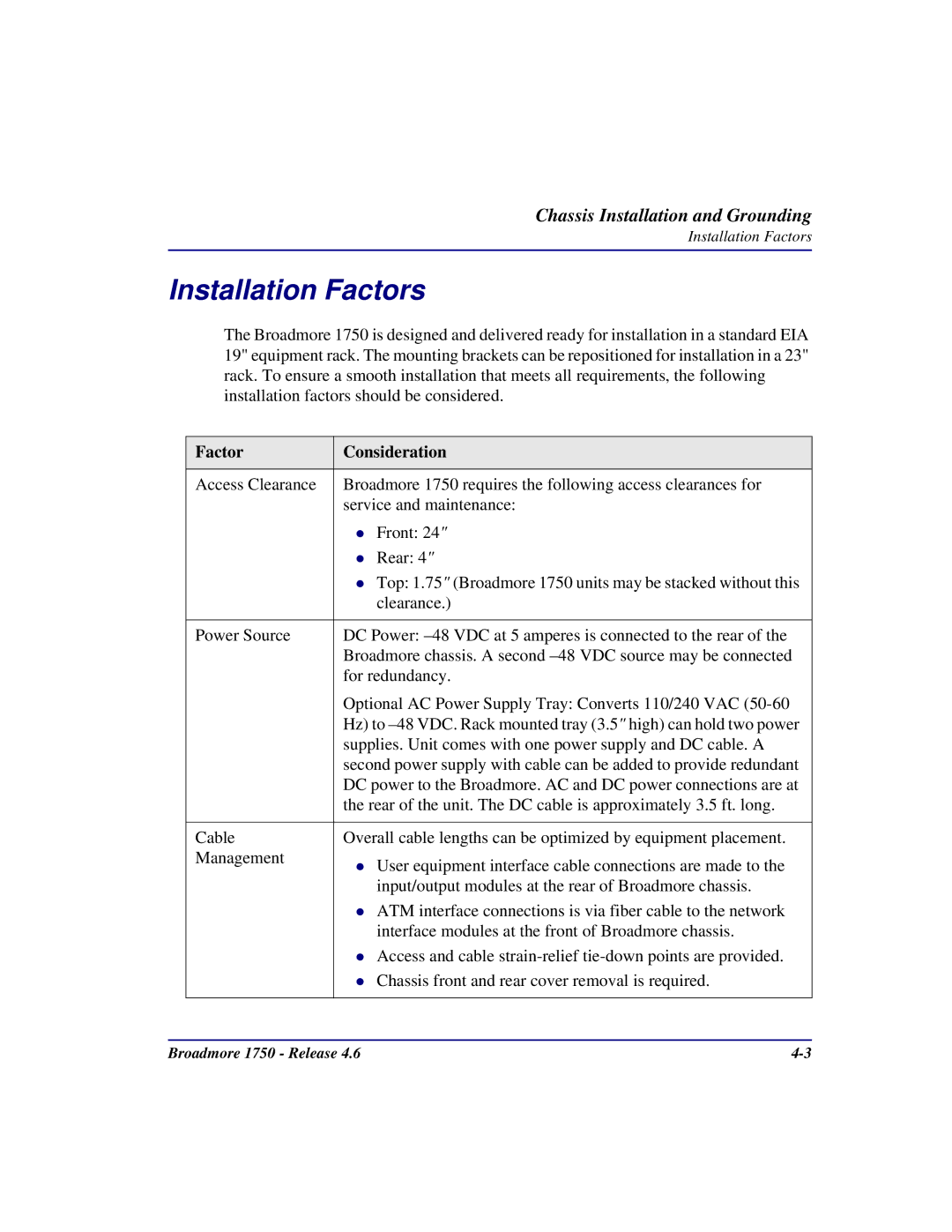
The Broadmore 1750 is designed and delivered ready for installation in a standard EIA 19" equipment rack. The mounting brackets can be repositioned for installation in a 23" rack. To ensure a smooth installation that meets all requirements, the following installation factors should be considered.
Factor | Consideration |
|
|
Access Clearance | Broadmore 1750 requires the following access clearances for |
| service and maintenance: |
| Front: 24" |
| Rear: 4" |
| Top: 1.75" (Broadmore 1750 units may be stacked without this |
| clearance.) |
|
|
Power Source | DC Power: |
| Broadmore chassis. A second |
| for redundancy. |
| Optional AC Power Supply Tray: Converts 110/240 VAC |
| Hz) to |
| supplies. Unit comes with one power supply and DC cable. A |
| second power supply with cable can be added to provide redundant |
| DC power to the Broadmore. AC and DC power connections are at |
| the rear of the unit. The DC cable is approximately 3.5 ft. long. |
|
|
Cable | Overall cable lengths can be optimized by equipment placement. |
Management | User equipment interface cable connections are made to the |
| |
| input/output modules at the rear of Broadmore chassis. |
| ATM interface connections is via fiber cable to the network |
| interface modules at the front of Broadmore chassis. |
| Access and cable |
| Chassis front and rear cover removal is required. |
|
|
Broadmore 1750 - Release 4.6 |
