Electrical Installation
Broadmore Power Input Connector
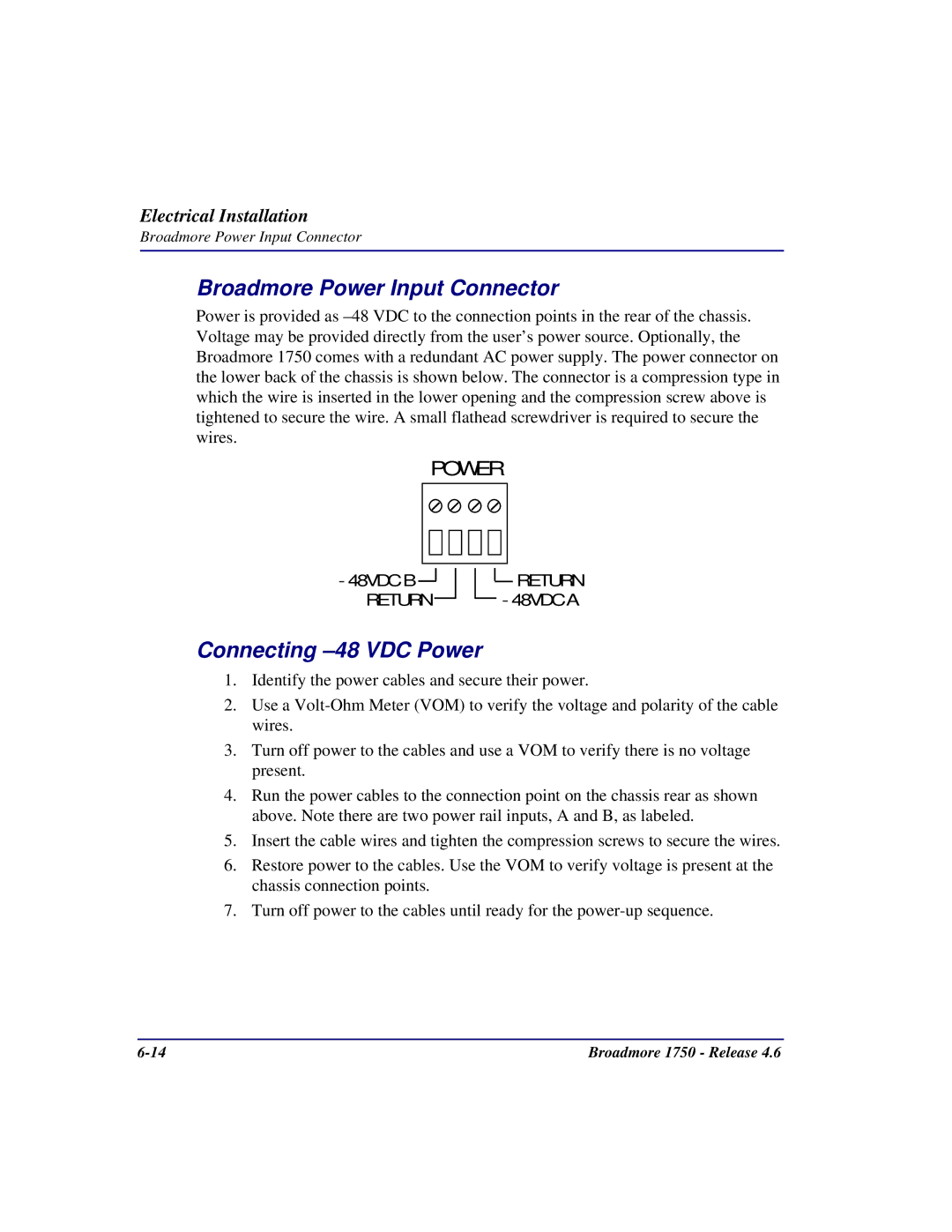
Broadmore Power Input Connector
Power is provided as
POWER
-48VDC B![]()
RETURN
![]() RETURN - 48VDC A
RETURN - 48VDC A
Connecting –48 VDC Power
1.Identify the power cables and secure their power.
2.Use a
3.Turn off power to the cables and use a VOM to verify there is no voltage present.
4.Run the power cables to the connection point on the chassis rear as shown above. Note there are two power rail inputs, A and B, as labeled.
5.Insert the cable wires and tighten the compression screws to secure the wires.
6.Restore power to the cables. Use the VOM to verify voltage is present at the chassis connection points.
7.Turn off power to the cables until ready for the
Broadmore 1750 - Release 4.6 |