DR4300 Circular Chart Recorder Product Manual
Revision I December
DR4300 Circular Chart Recorder
DR4300 Circular Chart Recorder Product Manual 12/03
Contacts
Abstract
References
Symbol Definitions
Symbol Definition
Contents
141
157
DR4300 Circular Chart Recorder Product Manual Vii
161
211
199
203
225
Tables
DR4300 Circular Chart Recorder Product Manual 12/03
Figures
Page
CE conformity Europe
Introduction
Function
Analog inputs
Communications
Relay outputs for control and alarms
Timer and totalizer options
Analog output for control or retransmission
Construction
Configuration
Self-diagnostics
Model number format
Model Number Breakdown
Introduction
Key numbers
Pen One
Model Number Table I Output
Description Model No Availability
Pen Two
Model Number Table II Instrument Options
Instrument Power/Transmitter Power
Product Configuration
Door Options
Model Number Table V APPROVALS/CERTIFICATES
Model Number Table III PEN 1 Options
Model Number Table IV PEN 2 Options
Future
DR4300 Circular Chart Recorder
About This Manual
All models described
Trouble?
Overview
Pre-installation information
Installation
What’s in this section?
Operating Limits and Condensed Specifications
Operating limits
Calibrated width of 100 mm 4 inches
Requirements
1000 ft One Pen Purple Two Pen Purple pen 1 and red pen
Screw terminals 2 piece
Modbus Communication
Transmitter Power
Open Collector Output
Digital Inputs
Dimensions
Mounting Considerations and Overall Dimensions
Overall dimensions
Physical considerations
Introduction
How to remove knockouts for conduits
Mounting Methods
Overview
Mounting Flush in a New Panel Cutout
Procedure
Mounting Flush in Panel New Panel Cutout
Step Action
Do not tighten the bolt at this time
Panel Mounting Recorder with NEMA4 or Heavy Duty door
Do not tighten the hex bolts at this time
Panel Mounting Recorder with NEMA4 or Heavy Duty Door
Side View
Pipe Mounting Procedure
Mounting on a 2-inch pipe
Mounting on Surface of Panel or Wall
Mounting Flush on a Surface of Panel or Wall
Electrical considerations
Wiring Prerequisites
Wiring should be performed by qualified personnel
Recorder grounding
Taking electrical noise precautions
CE conformity special conditions Europe
Recommended wiring routing
Recommended Wiring Routing Models Without CE Mark
Recommended Wiring Routing Models With CE Mark
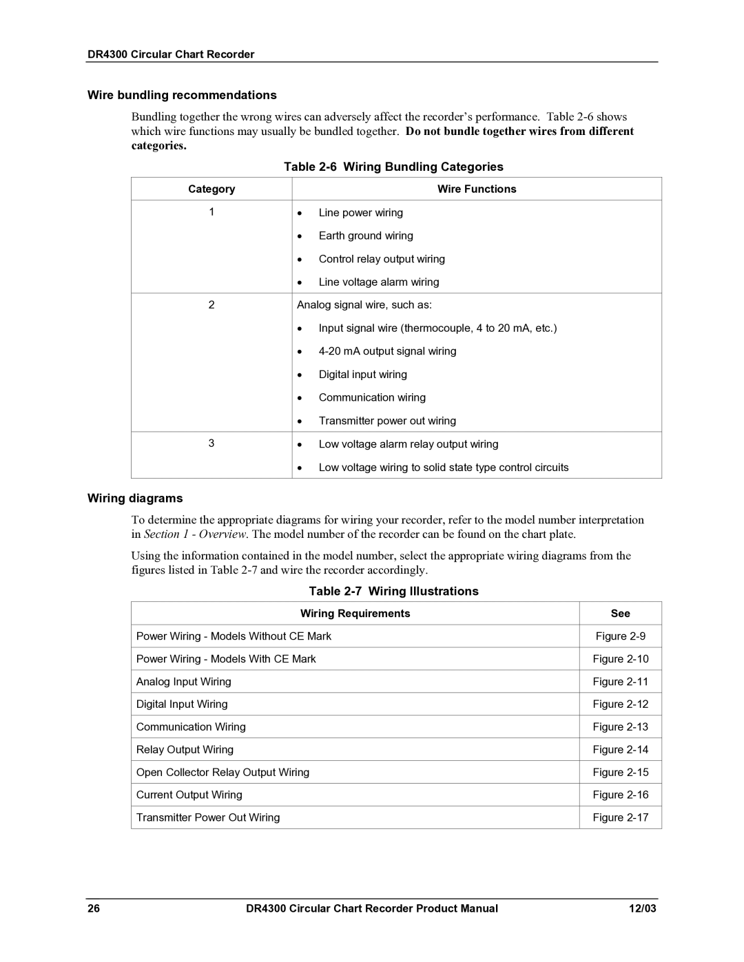
Wiring diagrams
Wire bundling recommendations
Wiring Bundling Categories
Wiring Illustrations
Shock Hazard
Input Wiring
Power Wiring
Procedure for Power Wiring Models
Power Wiring Models Without CE Mark
10 Power Wiring Models With CE Mark
Analog Input Wiring
Analog Input Wiring
11 Analog Input Wiring
10 Digital Input Wiring
Digital Inputs Optional
12 Digital Input Wiring
11 Communication Wiring
Communication Optional
13 Communication Wiring
Output Wiring
Discrete Outputs
Insulation of output wires
13 Relay Output Wiring 1 or 2 Pen Models
Electromechanical
To 30 Vac
14 Current Output Wiring
Current Output
16 Current Output Wiring
Transmitter Power Out
15 Transmitter Power Out Wiring
17 Transmitter Power Out Wiring
TB2
Following is a list of topics covered in this section
Procedure for Configuring Model without Display
Configuration Recording Set Up
Setting Configuration and Input Switches
S2 = Reset S3 = Lower S4 = Raise AC Power
Configuration
Switches
Run/Setup Switch
On off off on on off off off Off = Dont care
Configuration Switch S1 Input Switch S6
Summary of Input Set Up Switch S6 Functions
Chart Part R56
= off = on
Default setting
Day Any linear chart
= off = on
= off = on
= off = on
= off = on
SW1
50 to 50 Even 212 24 Hr
To 100 Even 116 1661-001 Day
To 200 Even 131 1660-010 24 Hr
Factory Configuration
Day 80 to 20 Even 269
To 100 Even 238 1661-001 Day 239
IEC Alpha = 0.00391 all RTDs without an asterisk IEC Alpha =
Setting SW6 Switch
Off for RTD actuation
Startup and Operation of Recorder without Display
Overview
Preparing the Recorder for Operation
Preparing the Recorder for Operation
Step Action/Result
Procedure for Running the Step Test
Running the Optional Step Test
Graphic
Being careful of the shock hazard at TB1 , place run
Chart step pattern
DR4300 Circular Chart Recorder Step Action/Result Graphic
Startup Procedure
Startup
Page
Operation of Recorder with Display and Keypad
INP
Displays and indicators
Operator Interface on Recorder with Display and Keypad
OUT
Key functions
Configuration Recording and Output Set Up
DR4300 Circular Chart Recorder Key Function
Configuration Prompts
Diagram prompt hierarchy
For pen alignment-see of manual
REMSW1 REMSW2
Blank Toggle
For field calibration-see of manual
How to Get Started
Configuration Tips
Configuration Tips
Switch Settings
Safety precautions
SW6 Input Switch
Setting SW6 Burnout Switch Overview
SW6 switch 2 OFF for RTD
Location of Switches and Relays
Step Operation Press Result
Configuration Procedure
Configuration Procedure
DR4300 Circular Chart Recorder Step Operation Press Result
Input Parameter Definitions
Input Parameters Set Up Group
Input group prompts
Decmal
100 H*factory setting
Lin factory setting
Filter
Example
Bias
None factory setting
Burnout Protection Input Failure provides most input
Pen Parameter Definitions
Pen Parameters Set Up Group
Pen group prompts
CHT HI
Chart Parameter Definitions
Chart Parameters Set Up Group
Chart group prompts
Chtspd
Totalizer Function Definitions
Totalizer Parameters Set Up Group
Control group prompts
Total
TOT EU Engineering Units of Totalized Value
INP EU Engineering Units of Input Signal
SEC factory setting
TOT DP
Rstabl
Cutoff
Control Parameter Definitions
Control Parameters Set Up Group
ONE factory setting
Outalg
TIME/CURRENT Duplex Relay = Cool-Similar to
Full factory setting
ON/OFF factory setting
PROPORTIONAL-DERIVATIVE with Manual
Power UP Controller Mode RECALL-This
PROPORTIONAL-INTEGRAL-DERIVATIVE
Hysteresis Output Relay only is an adjustable
Control Output Direction -In what direction do
Failsafe Latching Enabled When the recorder goes
Fsmode Failsafe Mode Auto
Failsafe Latching Disabled When the recorder goes
MAN
Minutes PER Repeat or Repeats PER Minute
MIN factory setting
Minrpm
Accutune
Tuning Parameters Set Up Group
Two sets of PID constants
Fuzzy overshoot suppression
Fuzzy Overshoot Suppression Feature
Tuning group prompts
10 Tuning Parameter Definitions
Fuzzy
MIN
RPM
DR4300 Circular Chart Recorder Product Manual 103
Cycle Timer for Relay 1 -Use this to specify
Cycle Timer for Relay 2 -This prompt will be
Used for cooling control
11 Setpoint Ramp Parameter Definitions
Setpoint Ramp/Program Set Up Group
Setpoint ramp/program group prompts
12 Timer Parameter Definitions
Timer Set Up Group
Timer group prompts
Period
13 Alarm Parameter Definitions
Alarms Set Up Group
Alarms group prompts
A2S1VA
A2S1TY
A2S2TY
From the alarm setpoint by a value equal to A2 HYS
14 Auxiliary Output Parameter Definitions
Auxiliary Output Set Up Group
Auxiliary output group prompts
Auxout
Auxiliary Output LOW Scaling FACTOR-Use a
Deviation Process Variable minus Setpoint
4mA VA
Auxiliary Output High Scaling FACTOR-Use a
Communication group prompts
Communication Set Up Group
Introductions
15 Communication Parameter Definitions
Remote Switch Digital Inputs Set Up Group
Remote switch group prompts
DR4300 Circular Chart Recorder Product Manual 113
16 Remote Switch Parameter Definitions
Configuration, Startup, and Operation Recorder with Display
REMSW1
Lockout group prompts
Display Parameter Set Up Group
OFF factory setting
17 Display Parameter Definitions
18 Lockout Parameter Definitions
Lock Out Parameter Set Up Group
Set this group last
Lock
Configuration Record Sheet
Keep a record
DR4300 Circular Chart Recorder Product Manual 117
Recorder TAG Name
19 Limit Control Parameter Definitions
Limit Control Configuration
Special configuration for control and alarms
DR4300 Circular Chart Recorder Product Manual 119
Startup of Recorder with Display and Keypad
Preparing the Recorder for Startup
20 Preparing the Recorder for Operation
Additional automatic self-tests
21 Procedure for Running the Step Test
DR4300 Circular Chart Recorder Product Manual 121
Step Press Action/Result
DR4300 Circular Chart Recorder Step Press Action/Result
Refer to if step test fails
DR4300 Circular Chart Recorder Product Manual 123
Set chart time and apply power Procedure
22 Procedure for Setting Chart Time and Applying Power
Completing Preparation and Startup
Status of tests displayed
Diagnostic tests Tests run automatically
23 Power-Up Diagnostic Tests
Ramtst
Key Error message
Check the displays and keys Procedure
24 Procedure for Testing the Displays and Keys
DR4300 Circular Chart Recorder Product Manual 125
Step Operation Press Action/Result
Startup procedure Procedure
25 Procedure for Starting the Recorder
DR4300 Circular Chart Recorder Product Manual 127
Operator interface Display
Operation of Recorder with Display and Keypad
Monitoring Your Recorder
Indicator Definition when lit
Meaning of indicators
26 Meaning of Indicators
DR4300 Circular Chart Recorder Product Manual 129
Viewing the operating parameters Contents of display
27 Lower Display Operating Parameter Labels
Diagnostic Error Messages
28 Error Messages
Overview Actions an operator can initiate
INP Input indicator
Operator Functions
DR4300 Circular Chart Recorder Product Manual 133
Procedure for selecting manual or automatic mode
29 Procedure for Selecting Automatic or Manual Mode
Changing the Control Setpoint Procedure
30 Procedure for Changing the Control Setpoints
DR4300 Circular Chart Recorder Product Manual 135
Viewing and Changing Alarm Setpoints Introduction
31 Procedure for Displaying or Changing the Alarm Setpoints
FAC or FLD
Selecting Factory or Field Calibration Values Introduction
Present value
33 Procedure for Resetting Totalizer
Resetting the Totalizer Introduction
Reset procedure
Starting the Timer Introduction
34 Procedure for Starting Timer
DR4300 Circular Chart Recorder Product Manual 139
Resetting the Limit Controller Introduction
35 Procedure for Resetting Limit Controller
Limit controller operator interface
140
DR4300 Circular Chart Recorder Product Manual 141
Input and Output Calibration for Recorder with Display
Input Calibration Minimum and Maximum Range Values
Minimum and maximum range values
RTD
Equipment Needed for Calibration
Input Calibration Preliminary Information
Equipment needed
Disconnect the field wiring
DR4300 Circular Chart Recorder Product Manual 145
DIP switch settings
Input Calibration Set Up and Wiring
General Calibration Set Up
General set up procedure
Thermocouple Inputs Using a Compensated Calibrator
DR4300 Circular Chart Recorder Product Manual 147
Thermocouple Inputs Using an Ice Bath or Ice Point Reference
DR4300 Circular Chart Recorder Product Manual 149
RTD Resistance Temperature Detector Inputs
Set Up Wiring Procedure for Calibrating RTD Inputs
Millivolts, Volts and Milliamps inputs
Input Calibration Procedure Sequence
Input Calibration Procedure
Calibration procedure sequence
DR4300 Circular Chart Recorder Product Manual 151
Repeat this procedure for the other pen, if required
Current Output Calibration
10 Set Up Wiring Procedure for Current Proportional Output
DR4300 Circular Chart Recorder Product Manual 153
Calibrator connections
11 Procedure for Calibrating Current Output
DR4300 Circular Chart Recorder Product Manual 155
Disp SET
156
Routine Maintenance
DR4300 Circular Chart Recorder Product Manual 157
Chart hub
Replacing the Chart
Procedure for Replacing the Chart
Pens to the chart
Replacing the Ink Cartridge
Procedure for Replacing the Ink Cartridge
DR4300 Circular Chart Recorder Product Manual 159
Maximizing Pen Life
Maximizing Pen Life
Steps for maximizing pen life
DR4300 Circular Chart Recorder Product Manual 161
Topic
Application related problems
Types of problems
Installation related problems
Hardware and software related problems
Observable Symptoms of Failure
Observable Symptoms of Failure
Symptoms
Symptom Subsection
Troubleshooting Procedures
DR4300 Circular Chart Recorder Product Manual 165
Recorder Failure Troubleshooting
Troubleshooting Recorder Failure Symptoms
Pen Trace Troubleshooting
Troubleshooting Pen Trace Failure Symptoms
DR4300 Circular Chart Recorder Product Manual 167
Chart Rotation Troubleshooting
Troubleshooting Chart Rotation Failure Symptoms
Troubleshooting Erratic Pen Movement
Troubleshooting Erratic Pen Movement Symptoms
Alignment of Pen at Zero and 100 %
Procedure for Pen Alignment
DR4300 Circular Chart Recorder Product Manual 169
Step Action Graphic
DR4300 Circular Chart Recorder Step Action Graphic
Troubleshooting and Pen Alignment of Recorder with Display
DR4300 Circular Chart Recorder Product Manual 171
172
Troubleshooting Aids
Power-Up Diagnostic Tests
Self Diagnostics
Power up tests
Tests run automatically
View Status of Tests
Procedure for Displaying the Results of Self-Diagnostics
DR4300 Circular Chart Recorder Product Manual 175
All relevant messages are displayed
Error Messages
Background Tests
Configuration, Startup, and Operation Recorder with Display
Error Messages
Troubleshooting and Pen Alignment Recorder with Display
DR4300 Circular Chart Recorder Product Manual 177
P1 ERR
P2 ERR
DR4300 Circular Chart Recorder Product Manual 179
180
DR4300 Circular Chart Recorder Product Manual 181
Recorder with Display for instructions for
Operation of Recorder with Display Subsection
DR4300 Circular Chart Recorder Product Manual 183
Operation of Recorder with Display
Operation of Recorder with Display for procedure
Troubleshooting the Keypad and Display
10 Troubleshooting Keypad and/or Display Failure Symptoms
DR4300 Circular Chart Recorder Product Manual 185
Troubleshooting Relay Output
11 Troubleshooting Relay Output Failure Symptoms
Refer to Replacing Hardware
12 Troubleshooting External Alarm Function Failure Symptoms
Troubleshooting External Alarm Function
Troubleshooting Remote Switch Digital Input Function
DR4300 Circular Chart Recorder Product Manual 187
Troubleshooting Modbus Communications
14 Troubleshooting Modbus Communications
15 Procedure for Aligning Pen at Zero and Span
Alignment of Pen at Zero and Span
Troubleshooting and Pen Alignment Recorder with Display Step
DR4300 Circular Chart Recorder Product Manual 189
190
Parts List
DR4300 Circular Chart Recorder Product Manual 191
Door assembly
Exploded Views
Chart plate
DR4300 Circular Chart Recorder Product Manual 193
Basic recorder components without options
Recorder Components
Basic Recorder Parts
Upgrade PROMs
DR4300 Circular Chart Recorder Product Manual 195
Parts Not Shown
Chart
DR4300 Recorder Non-CE Mark Internal Cabling Diagram
DR4300 Circular Chart Recorder Product Manual 197
198
Appendix a Accuracy
DR4300 Circular Chart Recorder Model Product Manual 199
Reference accuracy
Typical Reference Accuracy
Table A-1 Typical Reference Accuracy
Types of Input Range
± Degrees With Error Per 1 Degree Field Calibration Linear
DR4300 Circular Chart Recorder Model Product Manual 201
Factory Temp Stability Actuations
202
DAY
Single Range Charts
Table B-1 10-inch Single Range Chart Part Numbers
DR4300 Circular Chart Recorder Chart Type Range Units 24 HR
W5W26 Thermocouple
12/03 DR4300 Circular Chart Recorder Product Manual 205
RTD-PT100 a=0.00391
DR4300 Circular Chart Recorder Product Manual 207
RTD-PT100 a=0.00385
Calibration Range 24 HR
Dual Range Charts
Table B-2 10-inch Dual Range Chart Part Numbers
Appendix B Available 10-inch Charts Calibration Range 24 HR
DR4300 Circular Chart Recorder Product Manual 209
DR4300 Circular Chart Recorder Calibration Range 24 HR
Minimum purchase required
DR4300 Circular Chart Recorder Product Manual 211
Appendix C Setpoint Ramp/Soak Programming and Operation
Program Contents
Start segment number for each program
Guaranteed soak
Soak segments
End segment number for each program
Drawing a Ramp/Soak Profile
Ramp/soak profile example
DR4300 Circular Chart Recorder Product Manual 215
Profile graphs
216
DR4300 Circular Chart Recorder Product Manual 217
Profile worksheet
END
Setpoint Program Prompt Hierarchy
Table C-1 Prompt Hierarchy and Available Selections
Recycl
SG1 RP
Rpunit
END ST
SG2 SP
SG23RP
Or hour if Rpunit = EU-M Or EU-H Factory setting =
Limits factory setting =
SG24SP
Table C-2 Run/Monitor Functions
Run/Monitor the Program
Run/Monitor functions
XX HH . MM
REC.X
224
Appendix D Using Accutune
DR4300 Circular Chart Recorder Product Manual 225
Starting and Stopping Tuning with Accutune
Table D-1 Procedure for Starting Accutune
Step Press Action/Result Heating Tuning
Using Accutune with Duplex Heat/Cool Control
Table D-2 Procedure for Using Accutune for Duplex Control
DR4300 Circular Chart Recorder Product Manual 227
Until the value of Setpoint 2 is at the desired value within
Foreign Language Safety Instructions
DR4300 Circular Chart Recorder
DR4300 Circular Chart Recorder Product Manual 231
232
DR4300 Circular Chart Recorder Product Manual 233
234
DR4300 Circular Chart Recorder Product Manual 235
236
DR4300 Circular Chart Recorder Product Manual 237
238
¹¬¸ª¸ ¸»ª¸
240
Appendix F Honeywell Service Centers
DR4300 Circular Chart Recorder Product Manual 241
242
DR4300 Circular Chart Recorder Product Manual 243
Index
Ctralg parameter, 95, 100, 102, 103 current outputs
DR4300 Circular Chart Recorder Product Manual 245
Knockout locations, 16
Status set up group, 175 step test
DR4300 Circular Chart Recorder Product Manual 247
TB5 terminal
248
Page
Industrial Measurement and Control