Peripheral Units
Connection
Basic Parameters Extended
Marking
Precautions
Symbols Meaning
Limited applications
Handling in general
Transportation・Installation
Wiring
About operation
Sticking warning labels
When selecting the retry mode Applicable to inverters
About inspection and maintenance
About disposal of inverters
Ⅱ. Preface
Features
Special
Type Form Specification code
200V-3.7kW
Package Name plate
Panel description
Indication alphabet
Panel indication
Indication number
Page
VFA7-2300P, 4300P VFA7-4370P1~4550P1
VFA7-2185P, 2220P VFA7-4185P, 4220P
Grounding terminal
Page
Page
P24
Detaching the terminal board front cover
High-speed operation at a frequency of 60 Hz or over
Comparison with commercial power operation
Adjustment of overload protection level
Operation in low speed ranges
Motor with a braking system
Braking of a motor after power shutoff
Load producing negative torque
Use of an inverter at a voltage other than the rated one
Power factor improving capacitor
Over-current protective function
Inverter capacity
Measures to be taken
Power supply Inverter
Influences of leakage currents and measures against it
Power supply
Installation environment
Resistor
Installation place
Installation
For closed-type
Applicable Calorific value
Heat radiation area Required Motor Inverter
Page
Normal attachment Heat-sink going out attachment Simple type
Heat-sink going out attachmentsimple type
Inverter, or the inverter could cause a shock or a fire
Connection
Prevention of radio noise
Control panel
Standard connection diagram for sink logicminus common
Standard connection
Motor Main circuit
Control Circuit
R46 R41
Control
*1 R20
R20 R46
Main circuit terminals
Explanation of terminals
R20 S20 P0, PA, PB, PC, PA1,PB1,PR1
Terminal symbol
Inverter internal circuit
R0, S0 R46, R41, R20, S20
Control circuit terminals sink logicminus common
Connect a 1mAdc full-scale ammeter or a
Output Default setting Operation frequency command
Output Default setting Output current. Connect a 1mAdc
Input Function Electrical Inverter internal
Common Programmable Inverter Controller
Switching logic
Input Common P24 Output Common CC
Common Input
Serial RS485 communication connector
Could get a shock
Motor is at a standstill, or you could get a shock
Sensor vector control Optional
Control modes of the VF-A7 inverter
Example of typical connection
Simple operation of the VF-A7 1 Speed control mode
1Operation from the terminalexternal signals
)Setting the frequency by a current signal 4 to 20 mA
Frequency setting
Speed setting mode selection parameter at
)Setting the frequency by voltage signals 0 to 10
Speed setting mode selection parameter at
)Setting the frequency by voltage signals 0 to 10 Vdc
)Setting the frequency by voltage signals 0 to +/-10Vdc
:Start the motor
Operation from the control panel [Control panel operation]
Example of control panel operation
Selecting a stop mode with the control panel
Setting a control mode
Simple operation of the VF-A7 2 Torque control mode
S4 Control mode Switching RR switching
When the motor is out of operation. If the monitor display
Mode setting parameter is set at Running
Polarity of torque command
Start/stop
Operation from the terminalexternal signal
Torque command
Torque control mode
)Torque setting by means of a volume control
Torque setting by means of current signals 4 to 20 mAdc
Torque setting by means of voltage signals 0~10 Vdc
)Torque setting by means of voltage signals 0~10 Vdc
Others
Operation from the control panel
Setting the start and stop modes
Selecting a torque command mode
Torque command
Stop :Stops the motor
Set the torque command
Example of control panel operation
RUN :Starts the motor
Status monitor mode Setting monitor mode
Setting parameters Setting monitor mode
Speed control mode
Torque control mode
Procedure for setting a basic parameter
How to set basic parameters Basic parameter
Basic parameter list
Procedure for setting an extended parameter
How to set extended parameters
Running frequency
Example of parameter setting
When the motor is out of operation.If the monitor
Display mode setting parameter is set at
Searching for a parameter and changing its setting
Basic parameters
Parameters that cannot be changed during operation
Optional analog terminal #2 meter adjustment
FM terminal meter selection FM terminal meter adjustment
AM terminal meter adjustment
Optional analog terminal #1 meter adjustment
・ Function
Setting the acceleration and deceleration times
Automatic acceleration/deceleration
=
Time s
Manually setting the acceleration and deceleration times
Change the parameter setting to automatic
Acceleration/deceleration enabled by pressing key
:Automatic V/f mode setting
Increasing starting torque/ energy-saving operation mode
If you fail to make the setting for vector control
VF-A7 inverter has been set to this control mode by default
Selecting an operation mode
Preset speed operation
Title Function Set value
Operation command
Mode selection
Speed setting mode
Panel stop pattern
Speed setting
Terminal FM-related parameters
Setting and calibrating meters
Title Function Adjustment range
・Function
Calibrating a meter when the inverter is out of operation
Resolution
Set the parameter at fixed output for meter
By setup, before the needle of meter begins to sway
Return the parameter setting to output current display
Frequency display mode.If the monitor display mode setting
Hz standard setting =
Factory default setting
:Standard setting mode selection
Hz standard setting =
Clearing accumulating operation time =
Factory default setting =
Reset of user-defined parameters =
Trip clear =
:Maximum frequency
Parameter setting
Maximum frequency
:Forward/reverse selection
:Base frequency #1
Upper and lower limit frequencies
Base frequency
:Upper limit frequency :Lower limit frequency
Motor control
Control mode selection
:Motor control mode selection
Constant torque characteristic Normal way of use
Automatically
Setting suitable for fans and pumps
:The torque Boost rate is adjusted
To increase the starting torque
Control by pressing the key
Value. Default setting Constant torque
Change the parameter setting to Sensorless vector
To set the V/F characteristic arbitrarily
5-point setting
※100% adjustment value 200V class 200V,400V class
This control mode involves the setting of the motor constant
~
Switching between speed control and torque control
: Motor control mode selection
Speed setting
Binary/BCD inputoptional
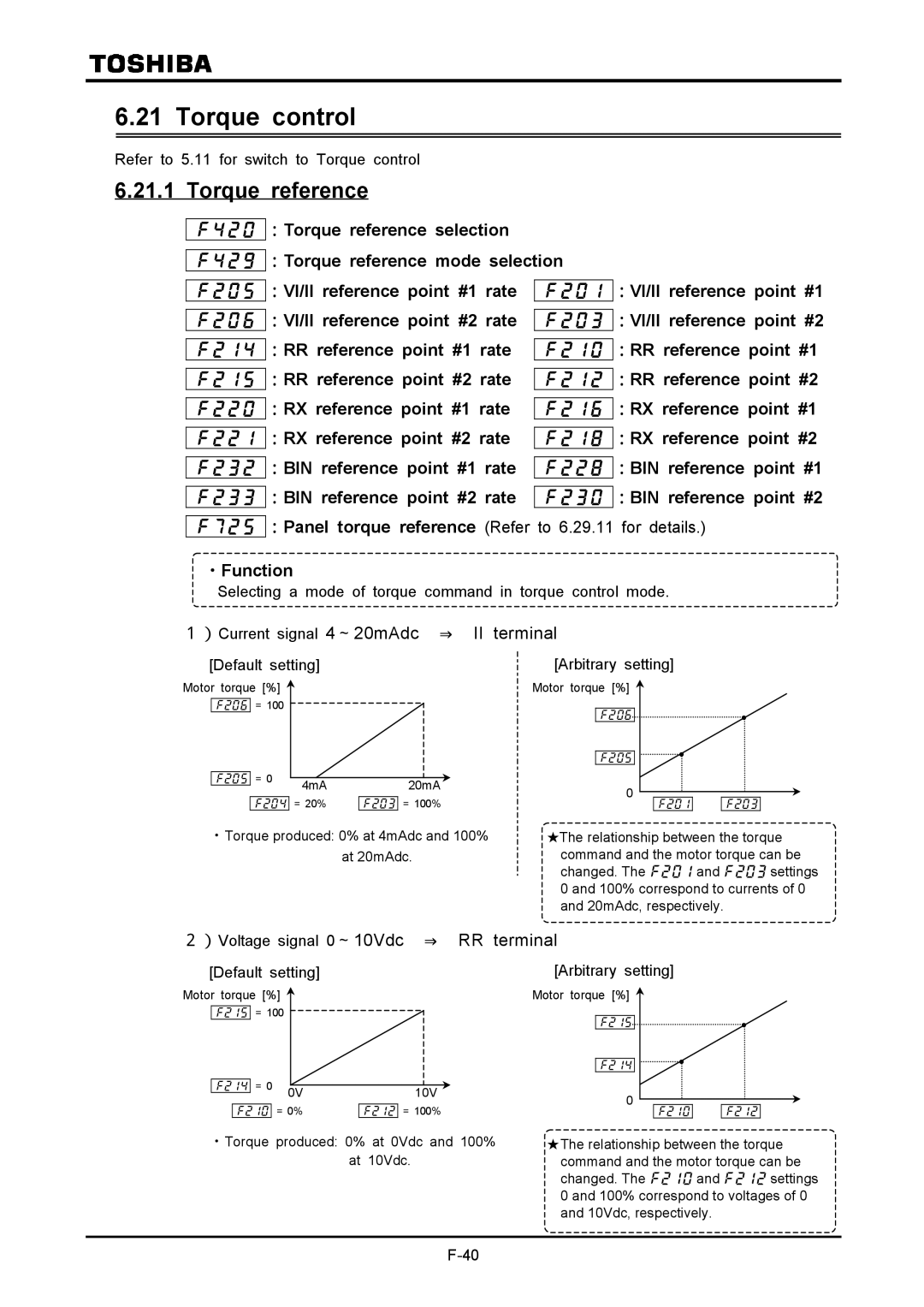
Torque reference
Common serial communication option
Communication add-on cassette option
Setting the electronic thermal protective function
Parameter Title Function Adjustment range
Manual boost ~ %
Overload stallSoft stall
Setting the electronic thermal protective function
Setting the motor overload protection level #1
Explanation of terms
×1.0 ×0.6
Setting of motor overload start level
Overload reduction start-up ~ Hz
Motor 150%-overload time limit
Inverter overload characteristic
Inverters overload protective characteristic
Start/stop
Preset-speed operation 15 speeds
Setting preset-speed frequencies
Preset-speed #2
Forward run command
Reverse run command
Preset-speed #1
Setting the operation mode
・Function
Frequency signals
Low-speed signal
・Output terminal setting
P24-OUT2
Putting out signals of arbitrary frequencies
・Function
Always-ON
Selection of input signals
Changing standby signal function
Standard
=Stop
[ Disabled Terminal board has no priority ]
Forward
Reverse
Setting value Jog run
Priority command from terminal board Operation command
terminal board has priority Enabled
Input terminal selection #8S4
Binary/BCD signal selectionExpansion TB option unit
:Binary/BCD signal selectionExpansion TB option unit
Forced JOG forward rotation
Changing input terminal functions
Signal on completion of acceleration/deceleration OUT
Selection of terminal functions
Keeping an input terminal function always active on
Refer to 7.2.3 for details
Changing output terminal functions
Response times of input/output terminals
Refer to 7.2.2 for details
Basic parameters #2
Setting of switching terminals
S1:V/f switching #1 S2:V/f switching #2
OFF
S1V/f switching #1 S2V/f switching #2 Parameters selected
has priority
Speed/torque command gain and bias
Using two types of frequency speed commands
has priority
Frequency reference
Command selected with
Setting frequency command characteristics
Setting torque reference characteristics
3 0Hz dead band frequency
Operating by means of reference signals
Operation frequency
Start-up frequency and End frequency
DC injection braking
DC injection braking
Forward/reverse DC braking priority control =OFF
Motor shaft fixing control
:Motor shaft fixing control
Braking under normal conditions
~ Hz
Zero-speed stop mode selection
:Zero-speed stop mode selection
LED display lights lights
Example of jog run
Jog run
:Jog run frequency :Jog stop control
~ Hz
Refer to 5.14 for details
Preset-speed #8~15
~ :Preset-speed #8~#15
Jump frequency Jumping resonant frequencies
PWM carrier frequency
Trip-less enhancement
:PWM carrier frequency
Restart of coasting motor Motor speed search function
Set the mode of Auto-restart
Restart after a momentary power failure
Set the control method of Auto-restart
Adaptation for elevator applications
1Case =
Case =~
Regenerative power ride-through control / Deceleration stop
Set the property of Auto-restart
Case =
:Retry selection
Retry function
~ Ω
Dynamic regenerative braking To urgently stop the motor
An internal braking resistor for 3.7kW model and smaller
Dynamic braking resistor capacity
120W 70Ω 200 120W 40Ω 400 120W 150Ω 100
An external braking resistor optional
Any value
Class Capacity kW
~ Ω Any value
When using a braking resistor without thermal fuse
PBR resistor capacity
Supply
Type
Selection of braking resistor option and braking unit
Connectable braking resistors and their minimum resistances
Avoiding over-voltage trip
Adjusting the output voltage and voltage compensation
:Reverse-run prohibition
Prohibiting the reverse operation
Speed at the drooping gain ~ Hz
Drooping control
Drooping Gain
Dead band Frequency
Function for crane/hoist
Commercial power/inverter switching
Timing chart
Speed feedback/positioning control
~ :Preset speed operation modes
PID control
Refer to 5.2 for details of this setting
Setting motor constants
Selection 1 Setting by the automatic V/f mode
Set the auto-tuning = Automatic tuning execution
Press the Enter key to activate the parameter
Setting parameter is set at Running frequency
Change the parameter setting to Automatic tuning
Motor is out of operation. If the monitor display momde
Setting the rating of the motor
①Slip frequency gain
Setting motor constants
Inverter VFA7 2037PL Motor 7kW, 4P, 60Hz Selection
Examples of setting auto-tuning
~10Vdc ⇒ RR terminal
Torque control
Torque reference
~20mAdc ⇒ II terminal
⇒ RX terminal
Voltage signal 0 ~± 10Vdc
Torque reference filter
:Torque reference filter
Setting of reverse speed limit level
Speed limits in torque control mode
Setting with the control panel
Setting of forward speed limit level
―― 40 ~20mA
Setting by means of external signals
Selection of external signals
Torque bias and load sharing gain
× +
Voltage signals Current signals
Setting of regenerative torque
Setting
Power running /regenerative torque limit
Setting of power running torque
Limiting the torque with external signals
Torque Limit #1
Regenerative Power running
Power running Regenerative
Positive/negative torque limits
Negative torque limit
RRvolume/ voltage
Positive torque limit
Selection Regenerative
Torque Limit
Suitable for the operation
Slowly in weak-field areas where it
Secondary acceleration/deceleration
Motor needs to be speeded up to
Selection with parameters
Switching of acceleration/deceleration #1, 2, 3
Acc/dec switching #1 Acc/dec switching #2
Output freq. Hz Setting freq
:Acceleration/deceleration lower limit
Parameter setting
Minimum acceleration/deceleration times
Acceleration/deceleration patterns
Pattern run
~
<Basic operating>
Monitor displayed during pattern run
④ :select pattern group #4 Parameter setting
Output frequency Hz Setting frequency Step trigger signal
Inverter trip holding
Motor over road protection-level adjust / motor types
Setting of current stall
Protection functions
Emergency stop by terminal operation
Emergency stop
Overload reduction start-up frequency
Motors 150%-overload time limit
Over-torque trip
Detection of output phase failure
Action at low currents
:Cumulative operation time alarm setting
Cooling fan control mode selection
Cumulative operation time alarm
:Cooling fan control mode
UV stall level
System-supporting sequence B-timer
Over-voltage stall protection level
Under-voltage trip
Special analog input
Additive over-ride
Over-ride
Output frequency = Reference × 1 + Over-ride %
Output frequency = Reference + Over-ride VI input Hz
Output frequency = Reference + Over-rideVI input Hz
Output frequency = Reference × 1 + Over-rideVI input %
Pulse output to meters
Setting of meter outputs
Setting of optional meter outputs
Meter output
Control panel parameters
Prohibiting the change of parameter settings
:Prohibition of parameter setting
:Current / voltage display mode
Display of the speed of the load
Display the motor speed and the load speed
:Frequency free unit magnification
Display of the rotating speed of the motor
Time 0.01 s
Changing items displayed in status monitor mode
Switching basic parameters
:Selection of panel V/f1, 2, 3 or
:Panel stop pattern
Resetting the inverter from the control panel
Panel reset function
Selecting a control panel stop pattern
Override in panel operation mode
Canceling PID control in panel operation mode
Setting a torque command in panel operation mode
Drooping control in panel operation mode
:Panel operation prohibition
Setting
Canceling methods
Restricting or prohibiting key operation
<Inter-drive communication>
Communication function RS485/common serial
Common serial optional device
<Computer link>
Setting of operation command common serial
Operation command ~ Mode selection
Terminal block enabled
Using the RS485 port fitted as standard
Inter-drive communications
:Wiring :Data (Host→Inverter)
:Wiring :Data (Master→slave)
Setting of operation command RS485
Setting of speed reference RS485
External Operation
Operation with External Signal
Connection method
Setting of contact input terminal function
Functions of input terminals in case of sink logic
Control terminal board
Example of use Push-type operation stop
Inverter
Acc/dec, V/f, torque limit #3
Table of contact input terminal function settings
Acc/dec, V/f, torque limit #2
Functions of output terminals in case of sink logic
Setting of output terminal functions
Symbol Title Function Adjustment Default setting
Low speed signal
Parameter setting
Or detected
OFF All the alarms above are cancelled
OFF in positive logic
Output of the designated data in 7 bits
Over travel On Over running
Completion of positioning On Positioning has been completed
Analog input filter
Setup of input/output terminal operation time
Setup of response time
Response time setting
Control terminal board
Setup of external speed command analog signal
Setting of analog input terminal functions
~
Setup by analog input signals RR terminal
Title Function Adjustment range
10V VI terminal
Setup by analog input signals VI/II terminal
Setup by analog input signals RX terminal
Status monitor
Status monitor mode
Information on input terminals
Information on output terminals
Type of connected option
Total accumulated operation hours
Changing status monitor function
Changing indication of status with power on
Changing contents of status monitor indication
1kW
FE30 Output power
01kW
Details of indications of trip status
Indication in trip status
Examples of reading out trip data
Indication of alarm, pre-alarm, etc
Failure, short-circuit or electric leak
Selection of wiring equipment
Inverter model
Selection of wiring equipment
Electromagnetic contactor in the primary circuit
Installation of electromagnetic contactor
Electromagnetic contactor in the secondary circuit
Installation of overload relay
VF-A7
Application and functions of options
Sorts of separate-type options
Motor end surge
RS-232C ⑬ communication converter unit Model RS2001Z
RS-232C Communication Converter cable
Selection table of separate-type options
Table of optional add-on cassettes
Optional add-on cassettes
Table of optional add-on cassettes
Functions of optional add-on cassettes
* In a set with SBP002Z
②Expansion TB option unit
* In a set with SBP001Z
Functions of board options
Installation of board option
Board options
Table of board options
Mandatory
Before installing optional add-on cassette or board option
Case
Preparation is not needed
Case 2-A. When PG feedback function is used
Prepare for installing according to 9.7.1, 1 to
Case 2-B. When PG feedback function is mot used
Basic parameters 1/2
Basic parameters 2/2
Terminal function selection 1/2
Frequency signal
Input signal selection
Extended parameters
Terminal function selection 2/2
Terminal response time setup
Basic parameters #2
Point Setting
Speed/torque reference gain/bias setup 1/2
Operation
Speed/torque reference gain/bias setup 2/2
Operation frequency
Braking
PWM carrier frequency
Preset speed operation frequency 8- to 15-stage speed
Tripless intensification setup 1/2
Jumper frequency
For lift 1/2
Tripless intensification setup 2/2
Control
Speed feedback/positioning control
Commercial/inverter switching function
Functions for lift 2/2
PID control
Vector control
Preset-speed operation mode
Torque control
Motor constant
Torque limit
Speed/torque reference gain/bias setup #21/2
Secondary acceleration/deceleration
Speed/torque reference gain/bias setup #22/2
Pattern run selection Disabled, 1 Enabled
Pattern run mode Patterned operation canceled during stop
Preset-speed #2 operation time Ditto
Preset-speed #1 operation
Continuation mode
Preset-speed #1 operation time ~8000 s / min
Protection functions
Meter output 1/2
Special analog input
Over-ride
Control Panel parameters
Meter output 2/2
Communication function1/2
Reservation area
Communication function2/2
[Contents of monitor indications]
Monitor FM/AM/pulse output function selection
Input terminal function setting 1/2
106 107 VI/II terminal priority 108 109
[Input terminal function setting 2/2]
= = =~ =
104 105
[Output terminal function setting 1/2]
[Output terminal function setting 2/2]
PWM
Default settings
Standard specifications by types
Standard specifications by types large capacity types
Common specifications
Digit
Fault
Process, upper/lower limits
Causes
External dimensions and mass
External dimensions and mass
Drawing E Drawing F
Outline drawings
Drawing a Drawing B
Drawing C Drawing D
Dimensions for heat-sink going out attachmentsimple type
・ Extend acceleration time #1
Indication Contents Expected causes Countermeasures
・ Decrease setting value
Also reset the
Main ROM fault
・ Reset the inverter
Initial read-error
Main RAM fault
・ If undervoltage is detected, set
Presence or absence of parameter trip can be selected
Setting signal apart from each
~ Caution! ~
Method of resetting causes of trip
RUN/STOP key
Is input power Input power Correct?
Make a service call
Is LED on
Measures against trouble with parameter setting
How to check other troubles
By feel touch
Regular inspection
Check points
Inspection method
・Dont replace any component part
Dealer for replacement of part
Periodical inspection
Points of inspection
Standard period of years to replace main component parts
Replacement of expendable parts
When retaining the inverter out of operation
When making a service call
Warranty
Disposing manner
Blasting during incineration
Plastics