Praesideo
Bosch Security Systems
FCC Requirements Class a
Important Safeguards
Disclaimer
Praesideo 3.5 Installation and User Instructions
Table of Contents
111
110
114
116
194
12.4
12.5
195
21.1
240
21.2
241
31.2
31.1
31.3
296
40.2
40.1
40.3
40.4
386
47.3
401
48.1
57.2
57.1
57.3
57.4
Emergency Sound Systems
List of authorized end-users Name Bosch Security Systems
Battery back-up / UPS back-up
EN60849 1998 compliancy checklist
EN60849 4.2 Responsible person
EN60849 4.3.2 Operational priorities
EN60849 4.4 Safety requirements
EN60849 5.2 Automatic status indication
EN60849 5.3 Automatic fault monitoring
Praesideo 3.5 Installation and User Instructions EN60849
EN60849 5.5 Interface with emergency detection system
EN60849 5.4 Monitoring of software controlled equipment
EN60849 5.6 Secondary power supply
EN60849 5.10 Connectors
EN60849 5.8 Marking and symbols for marking
EN60849 5.7 Climate and environmental conditions
EN60849 5.9 Electrical matching values
EN60849 6. Installation requirements
EN60849 7.2 Records to be kept
EN60849 7.3.2 Maintenance instructions
EN60849 7.3 Maintenance EN60849 7.3.1 General
Intentionally left blank
Clause / Requirement General requirements 4.1 General
EN54-16 2008 compliancy checklist
Compliance Signature Praesideo is compliant See Clauses 6 to
Praesideo 3.5 Installation and User Instructions EN54-16
Any kind of system information may be displayed during
Praesideo 3.5 Installation and User Instructions EN54-16
CIE
Clause / Requirement
Vacie may have provision for transmitting a signal that
Praesideo 3.5 Installation and User Instructions EN54-16
Praesideo 3.5 Installation and User Instructions EN54-16
Defective input or output for fault allocation. When an
Indicates no fault when open energized and indicates a
Praesideo 3.5 Installation and User Instructions EN54-16
Indication of the voice alarm zones in fault condition
Praesideo 3.5 Installation and User Instructions EN54-16
Praesideo system operates as an autonomous system
Compliance Signature
Becomes active. This assures that high priority
Praesideo 3.5 Installation and User Instructions EN54-16
Clause / Requirement Compliance Signature
Praesideo 3.5 Installation and User Instructions EN54-16
Clause / Requirement
Praesideo 3.5 Installation and User Instructions EN54-16
Praesideo 3.5 Installation and User Instructions EN54-16
Network controller is used to navigate through the menu, or
Sources with microphones
Vacie frequency response limits without microphones
Contains a switch-over relay to switch the loudspeaker load
Software documentation
Praesideo 3.5 Installation and User Instructions EN54-16
Monitoring of memory contents
Type number plate of each unit of the Praesideo system
EN54-16 2008 Vacie label
PRS-FINS
EN54-16 2008 products description
Additional clauses
ISO7240-16 2007 compliancy checklist
‘Emg x ISO8201 C’, with x being a sequential number
Each emergency loudspeaker zone shall be indicated
Containing one or more emergency loudspeaker zones
Praesideo 3.5 Installation and User Instructions ISO7240-16
Being displayed, independently of other indications
Changed clauses
ISO
Specimen shall be in the quiescent condition
Excluded clauses
Intentionally left blank
Praesideo on board of ships
Bosch Security Systems
Part 2 Introduction
Installation and User Instructions 2 Introduction
About this manual
System overview
Evacuation compliance
Reduced installation costs
External interfaces
High system flexibility
Call attributes
Calls
Types
Glossary
Part 3 Control Equipment
Intentionally left blank
PRS-NCO-B Network Controller
Rear view
Controls, connectors and indicators
Front view
Front and rear views of the network controller
12 13 14
Internal view of the network controller
Internal view
Connecting back-up power
Connecting the mains
Connections
Voltage selector and fuse
Connecting a PC
Connecting the network
Connecting audio inputs
Audio input types
Connecting control inputs
Connecting audio outputs
Right and left cinch connectors carry the same mono signal
Pin Socket Definition Description
Connecting RS232 port
Connecting control outputs
Compact flash card
Installation
Overview
Using the configuration menu
Navigate through the menu
Example
To jump back from a submenu to an item of the main Menu
To jump back from the main menu to the status Screens
Turn to move the cursor to the second part of the IP address
Faults menu
Configuration and operation
Start-up
Status screens
Main menu
Fault
11 Faults event table
Group a or B line fault
Fault input
Line supervision master mismatch
Pilot tone calibration
Supply
Redundant supply
Set date and time
Setup TCP/IP
Set monitoring options
View version information
View MAC address
Technical Data
Audio microphone inputs only input 1 and input
Audio line inputs
Control inputs
Audio outputs
Connector rear side
Headphones
Control outputs
13 RS232 interface
Network Redundancy Switching Audio outputs Control outputs
Controls & connectors
LBB4402/00 Audio Expander
Display + Control Audio inputs Control inputs
Front and rear views of the audio expander
See .3 for details about the audio input sockets
See .4 for details about the audio output sockets
Control outputs
Structure of the audio expander front panel menu
To navigate through a sub-menu
To jump to a sub-menu
To jump back from a sub-menu to an item of the main menu
Fault status
Version information menu items
Monitoring submenu
2A Serial Number 0.0030C
2B HW Version
Per system bus connector Data signal interface
Audio microphone inputs only input 1 and input
11 Maximum switching power
Display + Control CobraNet
LBB4404/00 CobraNet Interface
Connecting the Praesideo Network
Controls and connectors Connections
Connecting the CobraNet Network
Rear view
Front and rear views of the CobraNet interface
Connecting control inputs
CobraNet Configuration
Structure of the CobraNet interface front panel menu
Menu item screen elements
Cobranet Interf
CobraNet Fault Internal
Fault status severity high to low
2A Serial Number C.0.0030C
Technical data
Intentionally left blank
Part 4 Amplifiers
Bosch Security Systems
Number of inputs, spare amplifier
Power Amplifiers
Audio Inputs Spare Amplifier
Back-up
Controls, connectors and indicators
PRS-xPxxx, LBB4428/00
Voltage selector and fuse PRS-xPxxx
Ground connection
115 100 T6.3A H IEC 60127 or UL 230 220
Voltage range and fuse LBB4428/00
Number of amplifier channels
Connecting the amplifier channels
Loudspeaker lines
Power Amplifier 100
Spare amplifiers
5.3 50 V output
Main
Connecting a spare amplifier
Audio
Number of audio inputs
Type Audio inputs PRS-1P500 PRS-2P250 PRS-4P125 LBB4428/00
11 Supervised control input
48V
13 Connecting power amplifier to ground
Fan control
16 Installation
18 Structure of the power amplifier front panel menu
19 Menu item screen elements
Option value
Power Amp 4x125W
Status screen
10 Version information menu items
6 and further
2A Serial Number 0.0025B
All units in the system
Plastic optical fiber Network power consumption
Power supply
Back-up power
Power consumption PRS-1P500
Power consumption
Audio microphone inputs
Loudspeaker outputs and spare inputs
Derating
20 Output power derating
21 Maximum switching power
Bypass Audio Input + Loopthrough Control Inputs
LED Indicators Supervision
PRS-16MCI Multi Channel Interface
Front and rear views of the multi channel interface
Controls, connections and indicators
Basic amplifier interface connections
Connectors
Connecting to the basic amplifier
Jumper location
Connecting the multi channel interface by-pass
Supervised control inputs 1 to
10kΩ
Fail safe
Connecting the ground
Front panel LED indication
Multi channel interface and basic amplifier co-operation
Status LEDs
Network LED
Multi channel interface power supply
Basic amplifier connections
Audio Bypass
Basic Amplifiers
Block diagram of a basic power amplifier
Rear
Front
Front and rear views of the basic amplifier
Connecting to the multi channel interface
Connecting to the mains
+ + + + + +
Top view of the basic amplifier output boards
Spare Pilot
Pilot
11 Spare amplifier and loudspeaker Connections
Spare amplifier channel
Connecting the local audio input
15 Connecting back-up supply
X652
Operation
Battery LED status
Mains LED status
Channel LED status
MCI connection
Power consumption PRS-4B125
Power consumption PRS-1B500
Power consumption PRS-2B250
Twisted pair, shielded Input signal level
19 Maximum switching power
Single loudspeaker line supervision
Supervision-slave
Supervision-master
Installation
Supervision-master installation
Supervision-slave PCB dimensions
LBC 3018/00 Columns LBC 3210/00
Technical data supervision-master
Loudspeakers that have provision for a supervision-slave
Loudspeaker line characteristics
Technical data supervision-slave
Multiple loudspeaker line supervision
Power Amplifiers
X11
Supervision control board
Loudspeaker supervision board
Component side LBB4443/00
EOL supervision board
PRS-1P500, PRS-2P250, PRS-4P125 Power Amplifier
LC1-WM06E LC1-UM06E LC1-UM12E LC1-UM24E
X10 Lsp Out Lsp Out +
Addressing
S701S700
Technical data supervision control board
Technical data loudspeaker supervision board
Technical data EOL supervision board
=50±0.1= 4x10= = 40= ±0.17x =16= =60=
13 LBB4446/00 Brackets
Lsp Lsp +
14 LBC1256/00 Evac Connection Adapter
Intentionally left blank
Part 5 Call Stations
Installation and User Instructions 5 Call Stations
Keypad Network Processor
15 LBB4430/00 Call Station Basic
2K2 Microphone Headphone
Connecting a headset
Front and rear views
System status LED right
Power/Fault LED left
Call status LED center
Microphone
Physical data
Loudspeaker
Headset
Top view
16 LBB4432/00 Call Station Keypad
Call station or
Previous keypad
Bottom view
Configuration
Installation
Routing selector LED indications
Physical dimensions
Compatibility
PRS-CSNKP Numeric Keypad
Bottom view
Next keypad
Bottom view without lid
Display
Keys
Keys
Prompts
Technical data
Headset
18 LBB4433/00 Call Station Kit
X80 X11 X142 X70 X143
18.2 Controls, connectors
Indicators
Back-up supply
X4 connector details
X4 technical data
X11 technical data
X11 connector details
Mic+ Not connected PTT input contact
X70 connector details
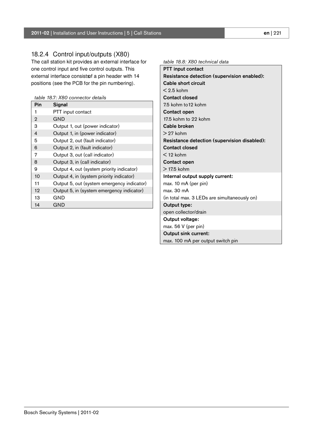
Pin Signal PTT input contact
X80 connector details
X80 technical data
Control input/outputs
62V
10 k Ω PTT Input Contact
100 mA Max Output X,
10 X142 technical data
X142 connector details
11 X143 connector details
External speaker
118 +
130
Dimensions H x W x D 130 x 118 x 20 mm Weight 120 g
19 LBB4434/00 Call Station Keypad Kit
X800 X810
19.2 Controls, connectors
X810 connector details
X800 connector details
100 mA
X810 technical data
150 Ω Output X, OUT
ID selector S9
X5 and X6 connector details
Keypad interface X5
10 Tyco AMP 169111-1 pliers
Technical data
PRS-CSR Remote Call Station
Controls, connectors and indicators
Connecting a power supply
Connecting control inputs
Red An emergency announcement is being made. Normal
Call station interface
External power supply
DB at -42 dBV/Pa and 1 kHz tolerance ± 3 dB Output power
PRS-CSRK Remote Call Station Kit
X300 X511 X301 Bosch Security Systems
X107 X501 X908
X2 technical data
Power supply/input contacts
X2 connector details
X501 technical data
X501 connector details
X301 connector details
Microphone X300
X107 connector details
LBB9082 connection diagram X301 technical data
X107 technical data
100 mA Max
10 Externally powered LED
11 X1 connector details
X511 connector details
10 X511 technical data
Installation
Electromagnetic compatibility
Connector RJ45 Cable type
PRS-CSI Call Station Interface
Fault Power Control Inputs External back-up Power 18 56
Network Redundancy Switching Cat.5
Exterior
Exterior
Interior
Connecting the network and remote call stations
Concept
Connecting a ground
Status LED indications
Dimensions H x W x D 27 x 243 x 80 mm Weight
1000 m Bosch Security Systems
PRS-CRF Call Stacker
Fault Power
Controls and indicators
Audio
Key cover
24 LBB4436/00 Key Covers
Part 6 Installation Accessories
Intentionally left blank
POF main
Controls and connectors
PRS-NSP Network Splitter
Exterior of the network splitter
Numbering in .4 differs from the numbering in .2 and figure
Tap-off
Connecting the main branch and creating tap-offs
Installation
Connector Kycon KPP4-P Input voltage 48 VDC
PRS-FIN, PRS-FINNA, PRS-FINS Fiber Interface
Controls, connectors Indicators
PRS-FIN, PRS-FINS PRS-FINNA
GOF 50m
Connecting POF and GOF cables
Tx Rx
Pin Description Transmitter Receiver
Kycon KPP-4P connector details
Control inputs technical data
Control inputs connector Control inputs connector details
26.3.5Operation
10 Installation
GOF connector
27 LBB4416/xx Network Cables
Pin Signal Wire +48VDC Copper
E1 E2 O1 O2
Data Optical fiber Bosch Security Systems
±0.1
Wiring
Custom-made cables
Connector
28 LBB4417/00 Network Connectors
Toolkit contents
29 LBB4418 Cable-connector Tool Kit
Toolkit supplier
Connector assembly drawing
Connector components
Cable types
Cable-connector installation
Preparation
= Red B = Brown
Crimping bush
Stripping copper wires
= Red
= Brown
11 Stripping a copper wire
Installing socket contacts
14 Crimping a socket contact
Stripping fibers
Do not forget to remove the piece of sheath From the tool
18 Cutting a fiber
21 Inserting a ferrule
Installing the ferrules
Data Optical fiber
Assembling the connector
30 Wiring diagram applied to type B optical network cables
29 Wiring diagram applied to type a optical network cables
AB R
35 Installing the front housing
Cable coupler
30 LBB4419/00 Cable Couplers
Part 7 System Hardware Installation
Intentionally left blank
Cabling
Both system connectors are identical
System bus
Data
Dust caps
Maximum distance
System may not contain more than 63 nodes
Maximum cable length
Nodes
Bending
Bending and coiling
Coiling
=110 mm
Basic system
Architecture
Redundant cabling
Network Controller Background music
Spare amplifiers
Tap-offs
CobraNet
Switch Ethernet backbone
Network Controller Praesideo
CobraNet Interface Ethernet
Failsafe
Connecting an alarm buzzer
IP Addresses
Rules
Connecting an alarm buzzer to the network controller
Power consumption
Power Consumption
Battery capacity calculation
Power consumption
Power sources
Cooling capacity
Change battery
Preventive maintenance
Clean air inlets
Intentionally left blank
Part 8 Software
Praesideo 3.5 Installation and User Instructions 8 Software
Installation on PC
Contents
PRS-SW Praesideo Software DVD
Mandatory packages
SVG viewer
Establishing connection
Praesideo core software
Correct communication
Upgrade system software
Praesideo web interface home
Upgrade firmware
Web interface start
10 Clear logging
Clear logging events
Release notes Manuals
Recommended packages
Adobe reader
Optional software packages
Optional packages
Security settings
Troubleshooting
Intentionally left blank
Part 9 System Configuration
Bosch Security Systems
Overview
Configuration software
Starting and logging on
Off-line configuration
Configure section
Saving
Submitting
Downloading configuration
Enabled items
Allowed characters
Unique names
Diagnose section
Upgrade section
Configuration printing utility
User management Add Delete
User management
Accounts
Add a user
Only Administrators can create new accounts
Delete user, step
Delete a user
Serial numbers
System definition
Serial number ranges addressable units
Network controller
Type no Description
Remote Call Station Call Station Interface
Add a power amplifier
Power amplifier
Delete power amplifier, step
42.4.2Delete a power amplifier
Audio expander
Call station
Add a fiber interface
Fiber interface CobraNet interface
Delete a fiber interface
Add a CobraNet interface
Delete a TCP/IP device
42.9 TCP/IP device
Add a TCP/IP device
Call Stacker
Multi Channel Interface
Procedure
Equipment configuration
Back-up power
Mains power
General
Supervision Off
Audio inputs
Level 18 to 12 dB
Output
Pilot tone On, Off
Pilot tone level To -18 dB
Make
Act on contact Break
Supervision On, Off
Actions
Default
Mains power fault grace
Time
2 h
Volume override output
Switch output
Fault alarm buzzer
Fault alarm indicator
Configure power amplifier, step
11 Configure power amplifier, step General configuration
Microphone Input gain To 7 dB mic
PRS-SVSET Single PRS-SVCO Multiple Configure supervision
Delay To 95108 ms PRS-1P500
To 47554 ms PRS-2P250
Pilot tone
Adding supervision devices
Line and loudspeaker supervision
Supervision devices and spare amplifiers
17 Add supervision device, step
20 Configure call station, step
Class Normal
General LBB4430/00
Emergency
Clear selection after call Yes
Power is failing, a fault event is generated
For 32 to 223 or Emergency for 32 to 255. When Class is
General LBB4433/00
Emergency the call station can make fail-safe calls
General PRS-CSR and PRS-CSRK
Back-up power Off
Remote call station
Call station interface
Unique name for the microphone audio input.
Microphone audio input can be enabled and disabled using
Checkbox
Off Input gain To 7 dB
Numeric keypad
Access Control
Access time-out
Act on contact Make
Control inputs LBB4433
Sets a part of the behavior of the control input
Various Sets the action of the control input See chapter
Key
Keypad
29 Configure audio expander, step
Fiber interface
31 Configure fiber interface step
35 Configure CobraNet interface step
39 Configure multi channel interface, step
Audio Outputs Spare Outputs
41 Configure multi channel interface, step
Mains power On, Off
17 Audio outputs configuration
Back-up power On, Off
Lsp connection Output a and B in same
Interconnection On, Off
18 Spare outputs configuration
Amplifier channel
Selection
43 Control inputs for multi channel interface
System wide settings Recorded messages System settings
System wide settings
Recorded messages
Register a recorded message
Creating a message set
Message sets
Unregister a recorded message
Transfer a message set
High efficiency alarm tones
11 System settings
System settings
Bosch Security Systems
Zone & amplifier
Zone configuration
Create a zone
Zone configuration, overview
Volume settings
Volume settings
Rename a zone
Delete a zone
Sparing
Zone Grouping
Add a zone group
Delete a zone group
11 Sparing, step
Each BGM channel must have a unique audio input
BGM Channels
Rename a BGM Channel
Add a BGM channel
Delete a BGM Channel
Call characteristics Call macro
Call characteristics
Call macro
Create a call macro
Add call macro, step
Delete a call macro
Momentary behaviors
Action programming
Behavior
Toggle behaviors
Single shot behaviors
Actions
47.3.4
47.3.3
47.3.5
47.3.6
This action can also be assigned to control inputs
Press-to-talk PTT
Call activation key
Stop
Start
Tones
Call macro
Recorded message
For information about available tones, see appendix a
Recall
Cancel selection
Zone selection
BGM source
Cancel last
Cancel all
BGM on/off
BGM volume control
Local BGM source
Local BGM volume control
Local BGM on/off
Fault input
Indicator test
Acknowledge/Reset
Synchronize time
Back-up power mode
Switch output
Switch trigger
Volume override output
Zone active output
Zone status
System fault
38 Zone status key
Zone priority status
Audio processing parameters
Audio processing
Bosch Security Systems
AVC calibration button
AVC calibration
Connection
Automatic volume control
Sensing microphones
AVC settings
AVC calibration running
Cable length margin
Diagnose installation
Number of nodes
Optical network
Device information
Loudspeaker supervision
Check configuration
Check configuration
Intentionally left blank
Part 10 Events
Praesideo 3.5 Installation and User Instructions 10 Events
Overview
Fault events
Introduction General events
Call events
Resetting fault events
General events list
Network connections set to half optical power Originator
Emergency state reset
Emergency state acknowledge
Emergency state active
User login
Network connections reset to full optical power Originator
User login failed
System restarted
Call events list
Call timeout
Call change
Call end
Fault events list
Amplifier overheat amplifier channel muted Originator
Backup power supply failure remote call station Originator
Back-up power supply failure
Cobranet interface fault or Cobranet network fault
Control input line failure control input
Configuration file version mismatch
Flash card data error
Invalid Firmware version
Incompatible hardware version
Line input failure
Loudspeaker line failure
Network power supply failure remote call station Originator
Pilot tone calibration failure
Processor reset
Redundant supply
SCB failure / Supervision Control Board failure Originator
Part 11 Optional Software
Intentionally left blank
CobraNet Discovery
Manually assigning an IP address
Network adapter configuration
IP address assignments
Snmp columns
MAC Address
IP Address
Menus
Firmware Update dialog
Network adapter
Options dialog
IP address range
Database location
Column Chooser dialog
Report functions
CobraNet Control and Configuration
Transmitter Configuration
CobraNet Configuration dialog
Receiver configuration dialog
Receiver Configuration
Advanced configuration dialog
Advanced Configuration
55.11.2DiscoOptions dialog fields
DiscoOptions
55.11.1General usage
Requirements
Logging Server
Logging Server icon correct operation
Start
Status messages
Main window
Opening the main window
Database has reached its critical size. Recommended action
Stop
Add a system
Disable event logging for a system
Connections
Delete a system
Logging expiration
Overview
Expiration periods
Recent events
Database
Database file
Flush events
Security
Password in the Viewer/Network controller
56.7.5.1 Overview
Block. Otherwise, the Logging Server cannot
Logging Viewer
Logging viewer setup
Configuration
Logging viewer
File
Menu bar
View
System
Blocks
Logging status button
Logging Server and Viewer are OK
Logging Server and Logging Viewer operate correctly
PC Call Server
PC Call Server setup program
Firewall
PCCstConfig Login
PC Call Server Configuration Client
Workflow
Configure Network Controllers…
File
Configure Interconnections…
Get Configuration
Configure Predefined Calls…
Configure PC Call Station Zone Groups
Configure Layouts…
Configure Layout Images…
Configure PC Call Station Client Users…
Configure BGM Channels…
15 Selection of predefined calls
Configure PC Telephone Interface Client…
Configure SIP Users…
Configure PC Telephone Interface Client Users…
Enter License Key…
Configure Time Synchronisation…
Change Configuration Password…
About
Customization
25 PCCstImages.png
31A-C
Item list of PCCstImages
For emergency call
For business call, selected for emergency call
45F-H
34A-C
34F-H
Licensing
Login name and password are configured
PC Call Station Client
Predefined call selection buttons
User Interface
Make a call
60.6.2.4Zone status icons
60.6.2.2Call activation buttons
60.6.2.3Call progress bar
10 Disconnected zone
60.6.3.3BGM zone status icons
Change BGM settings
60.6.3.2BGM volume buttons
20 No control of zone
Click Optional PC telephone interface
PC Telephone Interface Client
Voice response menu
Want to make, followed by the hash or pound key
Sound files
Groups
At the moment. Please try again later
Incoming call
Voice response flow
To Hang up call
Hang up call Make calls
Network configuration
Linksys SPA3102 configuration
Pstn configuration
Device initialization
Isdn telephones
Disconnect detection
Scope
Open Interface
Part 12 Appendices
Intentionally left blank
Tones
Alarms
Chimes
Repeating
Down to 900 Hz in 2.5 s and repeating. Signal duration 60 s
Down, then followed by 1 s
Silence. Continuously repeating
Silence period 4s Silence period of 4 s
Test tones
KHz in 0.25 s, followed by
Sweep 2 kHz to 1 kHz in 0.25 s
Assembly
Kycon KPP-4P connector
Table C.1 Product index
Product index
Table C.1 Product index
Intentionally left blank