82540EP/EM, 82541xx, 82544GC/EI, 82545GM/EM, 82546GB/EB,
Software Developer’s Manual
Initial Public Release
Date Version Comments
Software Developer’s Manual
Contents
TCP Segmentation Use of Multiple Data Descriptors
Software Developer’s Manual Vii
Power Management 129 Introduction to Power Management
10.1.3
203
13.4.25
13.7.10
Appendix 82540EP/EM and 82545GM/EM Differences
Xiv
Overview
Scope
Network Side Features
Ethernet Controller Features
PCI Features
CSA Features 82547GI/EI Only
Host Offloading Features
Additional Performance Features
Technology Features
Additional Ethernet Controller Features
Register and Bit References
Conventions
Related Documents
Memory Alignment Terminology
Introduction
Architectural Overview
LAN a LAN B
External Architecture
PHY
AGC, A/D
Eeprom Flash
ECHO, Next Fext
1 PCI/PCI-X Core Interface
Microarchitecture
DMA Engine and Data Fifo
2 82547GI/EI CSA Interface
5 MII/GMII/TBI/Internal SerDes Interface Block
4 10/100/1000 Mb/s Receive and Transmit MAC Blocks
Eeprom Interface
6 10/100/1000 Ethernet Transceiver PHY
Little Endian Data Ordering
DMA Addressing
Flash Memory Interface
Example 2-1. Byte Ordering
IA Byte # LSB MSB
Ethernet Addressing
Intel Architecture Byte Ordering
Interrupts
TCP Segmentation
Hardware Acceleration Capability
Buffer and Descriptor Structure
Checksum Offloading
Architectural Overview
Packet Address Filtering
Introduction
Packet Reception
Receive Descriptor Rdesc Layout
Receive Data Storage
Receive Descriptor Format
Receive
Receive Descriptor Status Field
Receive Status RDESC.STATUS Layout
PIF Ipcs Tcpcs RSV Ixsm EOP
Receive Descriptor Errors Field
CXE
Receive Errors RDESC.ERRORS Layout
RXE IPE Tcpe RSV
RSV SEQ
PRI
Receive Descriptor Special Field
Special Descriptor Field Layout
PRI CFI Vlan
Receive Descriptor Fetching Algorithm
Receive Descriptor Fetching
Null Descriptor Padding
Receive Descriptor Write-Back
Receive Descriptor Queue Structure
Receive Descriptor Packing
Receive Descriptor Ring Structure
Receive Interrupts
Receive Timer Interrupt
Receive Interrupt Delay Timer / Packet Timer Rdtr
Packet Delay Timer Operation State Diagram
Receive Interrupt Absolute Delay Timer Radv
Small Receive Packet Detect
Receiver Fifo Overrun
8 82544GC/EI Receive Interrupts
Receive Packet Checksum Offloading
Receive Descriptor Minimum Threshold ICR.RXDMT
Packet Type HW IP Checksum HW TCP/UDP Checksum Calculation
Supported Receive Checksum Capabilities
Packet Type HW IP Checksum
MAC Address Filter
GC/EI Supported Receive Checksum Capabilities
Packet Type HW IP Checksum HW TCP/UDP Checksum
9.4 IPv6 Filter
Packet Transmission
SNAP/VLAN Filter
9.3 IPv4 Filter
Transmit Descriptors
Transmit Data Storage
Transmit Descriptor Legacy Descriptions
Transmit Descriptor Tdesc Layout Legacy Mode
Legacy Transmit Descriptor Format
Transmit Descriptor Tdesc Layout
CSS
Transmit Descriptor Description Legacy
CMD
STA
Ifcs EOP
Transmit Descriptor Command Field Format
10. Transmit Command TDESC.CMD Layout
IDE VLE Dext RSV
11. Transmit Status Layout
Transmit Descriptor Status Field Format
12. Special Field TDESC.SPECIAL Layout
Transmit Descriptor Special Field Format
5 TCP/IP Context Transmit Descriptor Format
13. Transmit Descriptor Tdesc Layout Type = 0000b
6 TCP/IP Context Descriptor Layout
Transmit Description Descriptor Offload
14. Transmit Descriptor Tdesc Layout
Dtyp
6.1 TCP/UDP Offload Transmit Descriptor Command Field
Transmit Description
Tucmd
82544GC/EI only
15. Command Field TDESC.TUCMD Layout
IDE RSV Dext TSE TCP
16. Transmit Status Layout
7 TCP/IP Data Descriptor Format
6.2 TCP/UDP Offload Transmit Descriptor Status Field
Popts
17. Transmit Descriptor Tdesc Layout Type = 0001b
Popts RSV STA Dcmd Dtyp Dtalen
TSE Ifcs EOP
7.1 TCP/IP Data Descriptor Command Field
18. Command Field TDESC.DCMD Layout
IDE VLE Dext
Reserved
7.2 TCP/IP Data Descriptor Status Field
19. Transmit Status Layout
RSV Txsm Ixsm
7.3 TCP/IP Data Descriptor Option Field
7.4 TCP/IP Data Descriptor Special Field
20. Packet Options Field TDESC.POPTS Layout
21. Special Field TDESC.SPECIAL Layout
Transmit Descriptor Ring Structure
Transmit Descriptor Ring Structure
Transmit Descriptor Write-back
Transmit Descriptor Fetching
Transmit Interrupts
Delayed Transmit Interrupts
Transmission Process
Assumptions
TCP/UDP Data FCS
TCP Segmentation Performance
Packet Format
TCP Segmentation Data Fetch Control
3936
TCP Segmentation Indication
TCP Partial Pseudo-Header Checksum
TCP Segmentation Use of Multiple Data Descriptors
Options
IP and TCP/UDP Headers
Version IP Hdr
Offset High Header Checksum
Type of service Version IP Hdr Length Fragment
Fragment Offset Low
Byte1 Byte0 Destination Port
Destination Port Sequence Number
TCP Header
Length Checksum Urgent Pointer Options
Byte3 Byte2 Byte1 Byte0
Source Port Destination Port Length Checksum
Transmit Checksum Offloading with TCP Segmentation
17. UDP Pseudo Header Diagram for IPv4
9 IP/TCP/UDP Header Updating
19. Overall Data Flow
9.2 TCP/IP/UDP Header for the Subsequent Frames
9.1 TCP/IP/UDP Header for the First Frame
9.3 TCP/IP/UDP Header for the Last Frame
IP/TCP/UDP Transmit Checksum Offloading
Ipcss
Receive and Transmit Description
PCI
PCI Configuration
Mandatory PCI Registers
Address Description
Specification Update for the latest stepping information
Addr
Base Address Registers
Field Bits Read Initial Description Write Value
All base address registers have the following fields
Offset Space
Expansion ROM Base Address
Address Next Pointer
Capabilities Linked List
Bits Initial Value Description
PCI definition for more details
82547GI/EI
Status Register Layout
Byte Offset
PCI-X Configuration Registers
PCI-X Capability ID
Next Capability
Maximum Memory Read Byte Count. This register sets
PCI-X Command
Bits Read Initial
Write Value
Bits Read Intial Description Write Value
PCI-X Status
USC SCD
Reserved and Undefined Addresses
Command Register as follows
Bits Read Initial Description Write Value 05h
Message Signaled Interrupts1
Message Signaled Interrupt Configuration Registers
MSI Capability ID
Message Control
3.1.6
Commands
3.1.4 Message Address
3.1.5 Message Upper Address
Transaction Cause PCI Commands PCI-X Commands
Accepted PCI/PCI-X Command as a Target
PCI Commands Abr PCI-X Commands
Transaction Target PCI Commands PCI-X Commands
Memory Write Operations
PCI/PCI-X Command Usage
MWI Bursts
Master Write Command Usage Algorithm
Rules for Memory Read Operations
PCI-X Command Usage
Memory Read Operations
MW Bursts
Outstanding Memory Read
Cache Line Information1
Target Transaction Termination
LAN Disable
Interrupt Assignment 82547GI/EI Only
CardBus Application 82541PI/GI/EI Only
General Overview
Eeprom Interface
Stepping Vendor ID Device ID Description
Component Identification Via Programming Interface
Component Identification
Eeprom Device and Interface
Signature and CRC Fields
Software Access
Command Line Parameters
Eeupdate Utility
For the 82541xx and 82547GI
Eeprom Address Map1
Ethernet Controller Address Map
Word Used Bit Image
82546GB/EB only
LAN a
82545GM 82540EP
82541xx and 82547GI/EI only
82545GM
82541xx
ASF
82540EP/EM
Address Hi Byte Low Byte
Word Description Default HW Access
GC/EI and 82541ER Eeprom Address Map
Bit Name Description
Ethernet Address Words 00h-02h
Software Compatibility Word Word 03h
Software Compatibility Word Word 03h
PBA Number Word 08h, 09h
SerDes Configuration Word 04h
Eeprom Image Version Word 05h
Compatibility Fields Word 05h 07h
Initialization Control Word 1 Word 0Ah
Initialization Control Word 1 Word 0Ah
Subsystem Vendor ID Word 0Ch
Subsystem ID Word 0Bh
Initialization Control Word 2 Word 0Fh
Device ID Word 0Dh, 11h1
Vendor ID Word 0Eh
Initialization Control Word 2 Word 0Fh
82541PI/GI Only
OEM Reserved Words Words 10h, 11h, 13h 1Fh
Common Power Word 12h
Software Defined Pins Control Word 10h1, 20h
PHY Register Address Data Words 10h, 11h, and 13h 1Eh
Software Defined Pins Control Word 10h, 20h
Bit Description Default
CSA Port Configuration 2 Word 21h
CSA Port Configuration 2 Word 21h
Reserved Words 23h 2Eh
20 D0 Power Word 22h high byte
21 D3 Power Word 22h low byte
Circuit Control Word 21h
82541PI/GI/EI and 82547GI/EI Only
10. Initial Management Control Register Settings
Management Control Word 13h1, 23h2
11. SMBus Slave Address
SMBus Slave Address Word 14h1 low byte, 24h low byte
For Address 24h High Byte / LAN a
Initialization Control 3 Word 14h1 high byte, 24h high byte
12. Initialization Control
82546GB/EB uses INTB#
28 IPv6 Address words 17h 1Eh1 and 27h 2Eh
LED Configuration Defaults Word 2Fh2
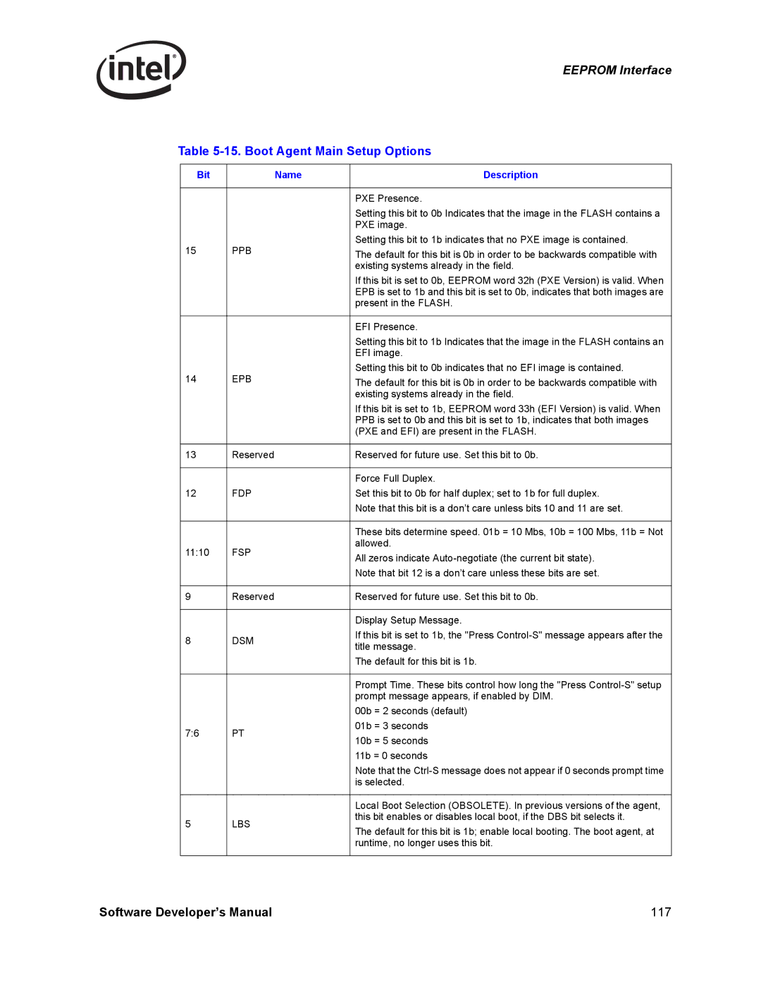
Boot Agent Main Setup Options Word 30h
27 IPv4 Address Words 15h 16h1 and 25h 26h
15. Boot Agent Main Setup Options
BBS
Boot Agent Configuration Customization Options Word 31h
DBS
DFU
16. Boot Agent Configuration Customization Options Word 31h
SIG
Mode
17. Boot Agent Configuration Customization Options Word 32h
Boot Agent Configuration Customization Options Word 32h
18. IBA Capabilities
IBA Secondary Port Configuration Words 34h-35h
IBA Capabilities Word 33h
Eeprom Images
19. WOL Mode and Functionality Word 0Ah
20. WOL Mode and Functionality Word 20h
Checksum Word Calculation Word 3Fh
Number
Parallel Flash Memory
21. Flash Memory Manufacturers
Manufacturer
124
Flash Interface Operation
Flash Control and Accesses
Write Accesses
Read Accesses
Flash Buffer Write Cycle
128
Assumptions
Introduction to Power Management
D3cold support
Power States
1.2 D0u State
Dr State
1.4 D3
Timing
1.3 D0a D0 active
Diagram #
Power Up Off to Dr to D0u to D0a
Transition from D0a to D3 and Back Without PCI Reset
Transition From D0a to D3 and Back Without PCI Reset
RST#
Transition From D0a to D3 and Back with PCI Reset
PCI Reset Sequence
PCI Reset Without Transition to D3
Next Item Pointer Byte Offset = 1 RO
PCI Power Management Registers
Bits Default Description
Capability ID Byte Offset = 0 RO
Eeprom
Power Management Capabilities PMC 2 Bytes Offset = 2 RO
Reserved
Software Developer’s Manual 139
Byte Offset = 7 RO
Pmcsrbse Bridge Support Extensions
3.6 Data Register
Byte Offset = 6 RO
Wakeup
Advanced Power Management Wakeup
Acpi Power Management Wakeup
Directed Exact Packet
Wakeup Packets
Pre-Defined Filters
Offset Field Value Action Comment
3.1.3 Broadcast
Directed Multicast Packet
3.1.4 Magic Packet*1
Offset Field Value Action Comment Bytes
ARP
3.1.5 ARP/IPv4 Request Packet1
+ S a
+ D + S a
Offset # of bytes Field Value Action Comment
Directed IPv4 Packet1
Directed IPv6 Packet1
+ D + S
IPX Diagnostic Responder Request Packet Example1
Flexible Filter
+ S
3.4 IPv6 Neighbor Discovery Filter1
Directed IPX Packet Example
CRC
Wakeup Packet Storage
152
Link Interfaces Overview
Ethernet Interface
1.2 8B10B Encoding/Decoding
Internal SerDes Interface/TBI Mode- 1Gb/s1
Code OrderedSet
Gmii 1 Gb/s
Code Groups and Ordered Sets
Code Group and Ordered Set Usage
MII 10/100 Mb/s
Internal Interface1
Duplex Operation
Half Duplex
Full Duplex
Packet Bursting
Carrier Extension 1000 Mb/s Only
Auto-Negotiation and Link Setup2
Auto-Negotiation and Link Setup1
Auto-Negotiation
Link Configuration in Internal Serdes/TBI Mode1
Link Speed
Hardware Auto-Negotiation
TXCW.txConfigWord
Bit Description
Software Auto-Negotiation
Forcing Link
Internal GMII/MII Mode
Forcing Speed
Using Auto-Speed Detection ASD
Comments Regarding Forcing Link
Automatic Detection of Link Speed using SPD-IND
Duplex
MII Management Registers
Control Bit Effect on Control Bits
Internal SerDes Mode1 Control Bit Resolution
Internal Serdes Mode1 Hardware Enabled
Internal Serdes1 Mode Software Enabled
Internal Serdes Mode1 Auto-Negotiation Skipped
Internal PHY Mode Control Bit Resolution
GMII/MII Mode PHY Speed Indication
GMII/MII Mode Force Speed
GMII/MII Mode Auto-Speed Detection
GMII/MII Mode Force Link
Loss of Signal/Link Status Indication
Internal Serdes Mode
Internal PHY Mode
Adaptive IFS1
10/100 Mb/s Specific Performance Enhancements
Register Name Description
Flow Control
MAC Control Frames & Reception of Flow Control Packets
10. Flow Control Registers
3x MAC Control Frame Format
Transmission of Pause Frames
Discard Pause Frames and Pass MAC Control Frames
External Control of Flow Control Operation1
Software Initiated Pause Frame Transmission
Packet #Octets
802.1q Vlan Packet Format
1 802.1q Tagged Frames
Vlan Packet Format Comparison
Stripping 802.1q Tags on Receives
Transmitting and Receiving 802.1q Packets
802.1q Vlan Packet Filtering
Adding 802.1q Tags on Transmits
VFE
Packet Reception Decision Table
178
Selecting an LED Output Source
Configurable LED Outputs1
Blink Control
Polarity Inversion
Blink Control
182
Auto-Negotiation
PHY Functionality and Features
Next Page Exchanges
Register Update
1000BASE-T
11.2 MDI/MDI-X Crossover copper only
Status
Pin
11.2.2 10/100 Downshift 82540EP/EM Only
Polarity Correction copper only
Link Down Energy Detect copper only
PHY Power Management copper only
Cable Length Detection copper only
11.4.2 D3 State, No Link Required copper only
11.4.3 D3 Link-Up, Speed-Management Enabled copper only
11.4.4 D3 Link-Up, Speed-Management Disabled copper only
Initialization
Mdio Control Mode
Overview of Link Establishment
Determining Link State
Determining Duplex State Via Parallel Detection
Configuration Result
False Link
Forced Operation
11.7.1 1000BASE-T
Link Criteria
Auto Negotiation
Parallel Detection
SmartSpeed
Using SmartSpeed
Link Enhancements
11.7.3 10BASE-T
Management Data Interface
Low Power Operation
Pause And Asymmetric Pause Settings
Asmdir Settings Pause Setting
11.11 1000 Mbps Operation
Powerdown via the PHY Register
Smart Power-Down
DSP ECHO, Next 4DPAM5
Transmit Fifo
Transmit Functions
Transmit/Receive Flow
Spectral Shaper
Low-Pass Filter
Line Driver
Receive Functions
Viterbi Decoder/Decision Feedback Equalizer DFE
11.12 100 Mbps Operation
11.13 10 Mbps Operation
Descrambler
PHY Line Length Indication
202
12.2.1 PCI/PCI-X interface
Features of Each MAC
Introduction1
204
IO BAR
MAC Configuration Register Space
12.2.3 SDP, LED, INT# output
Eeprom Arbitration
Shared Eeprom
Eeprom Map
Shared Flash
Flash Access Contention
Pin sampled LAN device controlled Enable/Disable
Values Sampled on Reset
Interrupt Use
Power Reporting
Multi-Function Advertisement
INTA#
Enabled
Summary
Interrupt Line Used
Register Conventions
Register Descriptions
Memory and I/O Address Decoding
Memory-Mapped Access to Internal Registers and Memories
Memory-Mapped Access to Flash
Memory-Mapped Access to Expansion ROM
Ioaddr
Ioaddr
Iodata
Offset Abbreviation Name Size
AD C/BE#30 Bits
Iodata Register Configurations
82547GI/EI only
Ethernet Controller Register Summary
Category Offset Abbreviation Name
82544GC/EI
Ipat 82544GC
Gprc
Xofftxc
Fcruc
PRC64
To the 82544GC/EI , 82541xx , or 82547GI
Category
Abbreviation Name Register
82544GC/EI , 82541xx , or 82547GI/EI
PCI-X Register Access Split1
Ctrl 00000h R/W
Main Register Descriptions
Device Control Register
Field Bits Initial Description Value
Ctrl Register Bit Description
Speed
SLU
Ilos
ADVD3WUC
Frcdplx
SDP0DATA
SDP1DATA
Field Bits Initial Description
Little-Endian Data Ordering
BEM = 0 64-bit mode Little-Endian
Device Status Register
Status 00008h R
Tbimode
Status Register Bit Description
Txoff
Pcixspd
Asdv
PCI66
Pcixmode
82544GC/EI Only
EEPROM/Flash Control & Data Register
Eecd 00010h R/W
Eecd Register Bit Description
Eesize
Eereq
Eegnt
Eepres
Eeprom Read Register Bit Description
Eeprom Read Register1
Eerd 00014h RW
Done Start
Eeprom Read Register Bit Description 82541xx and 82547GI/EI
FLA 0001Ch R/W
Flash Access1
Flash Access FLA
23 16
Extended Device Control Register
Ctrlext 00018h, R/W
10. Ctrlext Register Bit Description
Asdchk
SDP6IODIR
SDP2IODIR
SDP7IODIR
Linkmode
Vreg Power
11. GPI to SDP Bit Mappings
Down
CTRL.RST
Swdpinshi
12 GC/EI Ctrlext Register Bit Description
Swdpiohi
13 GC/EI GPI to SDP Bit Mapping
Mdic 00020h R/W
MDI Control Register
Phyadd
14. MDI Control Register Bit Description
RSV PHY REG Data
Regadd
PHY Registers
15. PHY Register Bit Mode Definitions
Register Mode Description
MSB
Field Bits Description Mode HW Rst SW Rst
242
LSB
Enaxc
RO,L
Software Developer’s Manual 245
246
For the 82541xx and 82547GI/EI
Pause
82544GC/EI only 82541xx
82541xx 82547GI/EI 82541xx and 82547GI/EI only
RF1
82544GC/EI Only
ANEG3
ANEG2
Software Developer’s Manual 251
23. Link Partner Ability Register Base Page Bit Description1
100BASE-TX
82541xx and 82547GI/EI Only
24. PHY Link Page Ability Bit Description1
10BASE-T
1b 82541xx
Software Developer’s Manual 255
Bits Field Description Mode HW Rst SW Rst
ANEG1
Master
ANEG0
MASTER/SLAVE
258
Software Developer’s Manual 259
DIS
NLP
SFD
Preen
Software Developer’s Manual 263
264
Software Developer’s Manual 265
266
82541/GI/ER and 82547GI B1
82541EI/82547GI B0 stepping
268
HCD
NOK
Software Developer’s Manual 271
272
Field Bits Description Mode HW Rst
Ledactled
SPEED1000LED
SPEED100LED
276
Software Developer’s Manual 277
To Perform Operation MDI Read/Write Sequence
Documented MDI Register 30 Operations1
51. MDI Register 30 Operations
Fcah 0002Ch R/W
Flow Control Address Low
Flow Control Address High
Fcal 00028h R/W
VET 00038h R/W
Flow Control Type
Vlan Ether Type
FCT 00030h R/W
57. Fcttv Register Bit Description
Flow Control Transmit Timer Value
Fcttv 00170h R/W
56. VET Register Bit Description
58. Txcw Register Bit Description
Transmit Configuration Word Register1
Txcw 00178h R/W
Rxcw 00180h R
Receive Configuration Word Register1
59. Rxcw Register Bit Description
LED1 ACTIVITY# LED0 LINKUP#
LED Control1
Ledctl 00E00h RW
ANC
60. LED Control Bit Description1
Mode Encodings for LED Outputs1
Mode Pneumonic State / Event Indicated
61. Mode Encodings for LED Outputs
Field Bits Initial Value Description
Packet Buffer Allocation
PBA 01000H R/W
62. PBA Register Bit Description
63. ICR Register Bit Description
Interrupt Cause Read Register
ICR 000C0H R
GPISDP6
RXT0
Mdac
Rxcfg
Interval
Interrupt Throttling Register1
ITR 000C4h R/W
64. ICS Register Bit Description
Interrupt Cause Set Register
ICS 000C8h W
To the 82544GC/EI
Interrupt Mask Set/Read Register
IMS 000D0h R/W
65. IMS Register Bit Description
IMC 000D8h W
Interrupt Mask Clear Register
66. IMC Register Bit Description
SBP
Receive Control Register
Rctl 00100h R/W
67. Rctl Register Bit Description
Rdmts
MPE
LPE
LBM
Cfien
BAM
Bsize
VFE
Secrc
Pmcf
Bsex
68. Fcrtl Register Bit Description
XON Enable 82544GC/EI , 82541xx , and 82547GI/EI only
Flow Control Receive Threshold Low
Fcrtl 02160h R/W
69. Fcrth Register Bit Description
Flow Control Receive Threshold High
Fcrth 02168h R/W
Rdbah 02804h R/W
Receive Descriptor Base Address Low
Receive Descriptor Base Address High
Rdbal 02800hR/W
RDH 02810h R/W
Receive Descriptor Length
Receive Descriptor Head
Rdlen 02808h R/W
Rdtr 02820h R/W
Receive Delay Timer Register
Receive Descriptor Tail
RDT 02818hR/W
Radv 0282Ch RW
Receive Interrupt Absolute Delay Timer1
Tctl 00400hR/W
Receive Small Packet Detect Interrupt1
Transmit Control Register
Rsrpd 02C00h R/W
TCTL.COLD
76. Tctl Register Bit Description
Cold
PSP
Nrtu
Transmit IPG Register
Tipg 00410R/W
Rtlc
IPGR2 IPGR1 Ipgt
77. Tipg Register Bit Description
IPGR2
Adaptive IFS Throttle AIT
Aifs 00458R/W
79. Tdbal Register Bit Description
Transmit Descriptor Base Address Low
Tdbal 03800h R/W
78. Aifs Register Bit Description
Tdlen 03808h R/W
Transmit Descriptor Base Address High
Transmit Descriptor Length
Tdbah 03804h R/W
82. TDH Register Bit Description
Transmit Descriptor Head
TDH 03810h R/W
Tidv 03820h R/W
Transmit Interrupt Delay Value
Transmit Descriptor Tail
TDT 03818h R/W
Txdctl 03828h R/W
TX DMA Control 82544GC/EI only
Transmit Descriptor Control
Txdmac 03000h R/W
Lwthresh RSV1 Gran RSV Wthresh Hthresh Pthresh
86. Txdctl Register Bit Description
Lwthresh
Transmit Absolute Interrupt Delay Value1
Tadv 0382Ch RW
Gran
Tspbp
TCP Segmentation Pad And Minimum Threshold Tspmt 03830h RW
Tspbp Tsmt
Software Developer’s Manual 319
Wthresh RSV Hthresh Pthresh
Receive Descriptor Control
Rxdctl 02828h R/W
87. Rxdctl Register Bit Description
3111
Receive Checksum Control
Rxcsum 05000h R/W
88. Rxcsum Register Bit Description
IPV6OFL
Ipofld
Tuofld
89. MTA Register Bit Description
Filter Registers
Multicast Table Array
MTA1270 05200h-053FCh R/W
Destination Address
RAH 05404h + 8∗n R/W
Receive Address Low
Receive Address High
RAL 05400h + 8*n R/W
RAH
Vlan Filter Table Array1
VFTA1270 05600h 057FCh R/W
91. RAH Register Bit Description
92. VFTA1270 Bit Description
Wakeup Registers
Wakeup Control Register
WUC 05800h R/W
SPM
Wakeup Filter Control Register
Wufc 05808h R/W
Apmpme
WUS 05810h R
Wakeup Status Register
330
Ipav 5838h R/W
IP Address Valid
Field Dword # Address Bits Initial Value Description
13.6.5 IPv4 Address
IP4AT 05840h 05858h R/W2
Address
Dword # Address Bits Initial Value Description
13.6.6 IPv6 Address
IP6AT 05880h 0588Ch R/W
IPV6ADDR0
Flexible Filter Length Table
Wakeup Packet Length
Wakeup Packet Memory 128 Bytes
LEN2
Flexible Filter Mask Table Ffmt 09000h 093F8h R/W
LEN0
LEN1
Ffvt 09800h 09BF8h R/W
Statistics Registers
Flexible Filter Value Table
Algnerrc 04004h R
CRC Error Count
Alignment Error Count
Crcerrs 04000h R
Rxerrc 0400Ch R
Symbol Error Count
RX Error Count
Symerrs 04008h R
SCC 04014h R
Missed Packets Count
Single Collision Count
MPC 04010h R
MCC 0401Ch R
Excessive Collisions Count
Multiple Collision Count
Ecol 04018h R
Colc 04028h R
Late Collisions Count
Collision Count
Latecol 04020h R
Tncrs 04034h R
Defer Count
Transmit with No CRS
DC 04030h R
Cexterr 0403Ch R
Sequence Error Count
Carrier Extension Error Count
SEC 04038h R
Xonrxc 04048h R
Receive Length Error Count
XON Received Count
Rlec 04040h R
Xoff Transmitted Count
XON Transmitted Count
Xoff Received Count
PRC64 0405Ch R
FC Received Unsupported Count
Packets Received 64 Bytes Count
Fcruc 04058h R
PRC255 04064h R
Packets Received 65-127 Bytes Count
Packets Received 128-255 Bytes Count
PRC127 04060h R
PRC1023 0406Ch R
Packets Received 256-511 Bytes Count
Packets Received 512-1023 Bytes Count
PRC511 04068h R
Gprc 04074h R
Packets Received 1024 to Max Bytes Count
Good Packets Received Count
PRC1522 04070h R
Mprc 0407Ch R
Broadcast Packets Received Count
Multicast Packets Received Count
Bprc 04078h R
Gorcl 04088h R/GORCH 0408Ch R
Good Packets Transmitted Count
Good Octets Received Count
Gptc 04080h R
Rnbc 040A0h R
Good Octets Transmitted Count
Receive No Buffers Count
Gotcl 04090h R/ Gotch 04094 R
RFC 040A8h R
Receive Undersize Count
Receive Fragment Count
RUC 040A4h R
RJC 040B0h R
Receive Oversize Count
Receive Jabber Count
ROC 040ACh R
129. RJC Register Bit Description
Management Packets Received Count1
Mgtprc 040B4h R
Total Octets Received
Management Packets Dropped Count1
Management Pkts Transmitted Count1
131. Totl and Toth Register Bit Descriptions
Total Octets Transmitted
Totl 040C8h R/W / Toth 040CCh R
130. Torl and Torh Register Bit Descriptions
TPT 040D4h R
Total Packets Received
Total Packets Transmitted
TPR 040D0h R
PTC127 040DCh R
Packets Transmitted 64 Bytes Count
Packets Transmitted 65-127 Bytes Count
PTC64 040D8h R
PTC511 040E4h R
Packets Transmitted 128-255 Bytes Count
Packets Transmitted 256-511 Bytes Count
PTC255 040E0h R
PTC1522 040ECh R
Packets Transmitted 512-1023 Bytes Count
Packets Transmitted 1024 Bytes or Greater Count
PTC1023 040E8h R
Bptc 040F4h R
Multicast Packets Transmitted Count
Broadcast Packets Transmitted Count
Mptc 040F0h R
Tsctfc 040FCh R
TCP Segmentation Context Transmitted Count
TCP Segmentation Context Transmit Fail Count
Tsctc 040F8h R
Rdfh 02410h R/W
Diagnostics Registers
Receive Data Fifo Head Register
Receive Data Fifo Tail Register
Rdfts 02428h R/W
Receive Data Fifo Head Saved Register
Receive Data Fifo Tail Saved Register
Rdfhs 02420h R/W
Tdfh 03410h R/W
Receive Data Fifo Packet Count
Transmit Data Fifo Head Register
Rdfpc 02430h R/W
Tdfhs 03420h R/W
Transmit Data Fifo Tail Register
Transmit Data Fifo Head Saved Register
Tdft 03418h R/W
Tdfpc 03430h R/W
Transmit Data Fifo Tail Saved Register
Transmit Data Fifo Packet Count
Tdfts 03428h R/W
152. PBM Bit Description
Packet Buffer Memory
PBM 10000h 1FFFCh R/W
151. Tdfpc Register Bit Description
370
General Configuration
Power Up State
Receive Initialization
General Initialization and Reset Operation
Transmit Initialization
Ipgt IPGR1 IPGR2
Fiber Copper 82544GC/EI
Signal Ball Name and Function
Signal Descriptions
Receive Clock
Signal Interface
Carrier Sense
Receive Data
MII 10/100 Mbps Differences
GMII/MII Features not Supported
Signal Functions
Signal Function Pin Gmii 1000 Mbps Operations
Direct PHY Indications to MAC
Avoiding Gmii Test Modes MAC Configuration
Signal Functions Not Supported
CTRL.FD
Link Setup
CTRL.RFCE
PHY Initialization 10/100/1000 Mb/s Copper Media
Lanpwrgood
Reset Operation
382
Software Developer’s Manual 383
Initialization of Statistics
Loopback
Diagnostics
Fifo State
Fifo Data
Internal Loopback
Testability
Bypass Instruction
Extest Instruction
SAMPLE/PRELOAD Instruction
Idcode Instruction
388
Appendix Changes From 82544EI/82544GC
New Features
EEC
Register Changes
Table A-1. Register Changes
Register Offset
Serial Flash Interface
82540EP/EM Differences
4 32-Bit PCI Support
No TBI/Internal SerDes Interface
Single-Port Functionality