Chapter 4 Cisco ASR 1006 Router Overview and Installation
Auxiliary Connection
Auxiliary Connection
This asynchronous
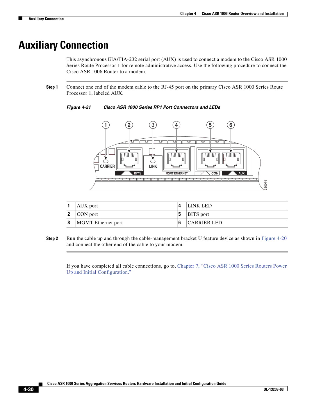
Step 1 Connect one end of the modem cable to the
Figure 4-21 Cisco ASR 1000 Series RP1 Port Connectors and LEDs
1 | 2 | 3 | 4 | 5 | 6 |
CARRIER | LINK |
|
|
BITS | MGMT ETHERNET | CON | AUX |
|
|
| 280079 |
1 | AUX port | 4 | LINK LED |
|
|
|
|
2 | CON port | 5 | BITS port |
|
|
|
|
3 | MGMT Ethernet port | 6 | CARRIER LED |
|
|
|
|
Step 2 Run the cable up and through the
If you have completed all cable connections, go to, Chapter 7, “Cisco ASR 1000 Series Routers Power Up and Initial Configuration.”
Cisco ASR 1000 Series Aggregation Services Routers Hardware Installation and Initial Configuration Guide
|
| |
|
