Chapter 5 Cisco ASR 1004 Router Overview and Installation
Equipment Shelf or Tabletop Installation
Step 4 Repeat Step 2 through Step 3 on the other side of the chassis. Use all the screws to secure the
Note The
Step 5 Obtain the two
Note Make certain that the
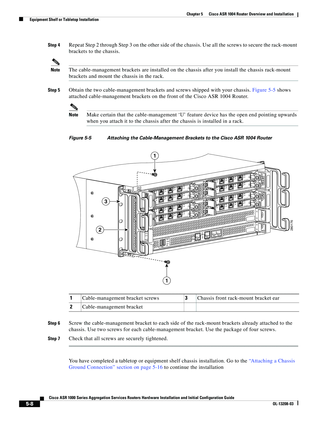
Figure 5-5 Attaching the Cable-Management Brackets to the Cisco ASR 1004 Router
1
3
|
|
|
| C/ | A |
|
|
|
|
| |
|
| C/ | A | A/ | L |
C/ | A | A | /L |
| 3 |
|
|
| |||
A | /L |
|
| 2 |
|
|
| 1 |
| C/A | |
0 |
| C/ | A | A/L | |
|
|
| |||
C/ | A | A/L |
|
| |
|
| 3 | |||
A | /L |
|
| 2 |
|
|
|
|
| ||
|
| 1 |
|
|
|
0 |
|
|
|
|
|
|
|
|
| C/A | |
|
| C/ | A | A/L | |
|
|
| |||
C/ | A | A/ | L |
| 3 |
|
|
| |||
A | /L |
|
| 2 |
|
|
| 1 |
| C/ | A |
|
|
|
|
| |
0 |
| C/ | A | A/ | L |
C/ | A | A | /L |
| 3 |
|
|
| |||
A | /L |
|
| 2 |
|
|
|
|
| ||
|
| 1 |
|
|
|
0 |
|
|
|
|
|
C/A |
| TATUS | |||
A/L | S | ||||
|
| ||||
|
|
|
| ||
C/A |
| T AT | US | ||
A/L | S |
| |||
|
| ||||
|
|
|
| ||
C/ | A |
| TATUS | ||
|
| ||||
A | /L | S |
|
| |
|
|
|
| ||
C/ | A |
|
| US | |
|
| T AT | |||
| /L | S |
| ||
A |
|
| |||
|
|
|
| ||
|
|
|
| C/A | |
|
| C/ | A | A/L | |
|
|
| |||
C/ | A |
| /L |
|
|
| A |
|
| ||
A | /L |
|
| 2 |
|
|
|
|
| ||
|
| 1 |
| C/A | |
0 |
| C/A | A/L | ||
|
| ||||
C | /A | A | /L |
|
|
|
|
| |||
A | /L |
|
| 2 |
|
|
|
|
| ||
|
| 1 |
|
|
|
0 |
|
|
|
|
|
|
| C/A | C/A | ||
|
| A/ | L | ||
C/ | A | A/L |
|
| |
|
|
| |||
A | /L |
|
| 2 |
|
|
|
|
| ||
|
| 1 |
| C/A | |
0 |
| C/A | A/ | L | |
|
|
| |||
C/ | A |
| /L |
|
|
| A |
|
| ||
A | /L |
|
| 2 |
|
|
| 1 |
|
|
|
0 |
|
|
|
|
|
C/ | A | TATUS |
A | /L | S |
|
|
|
|
| |
3 |
|
|
|
|
|
C/A |
|
| AT | US | |
A/L | S | T |
| ||
|
|
| |||
|
|
|
|
| |
3 |
|
|
|
|
|
C/ | A |
| TATUS | ||
A/L | S |
|
|
| |
|
|
|
|
| |
3 |
|
|
|
|
|
C/ | A |
|
|
| US |
|
| T A | T | ||
A/L | S |
|
| ||
|
|
| |||
|
|
|
|
| |
3 |
|
|
|
|
|
280176
2
|
|
|
|
|
|
| LINK |
| AUX |
|
|
|
|
|
|
|
| CON | |
|
|
|
|
|
| HD | CARRIER | MGMT | ETHERNET |
|
|
|
|
|
| USB | BITS |
|
|
|
| CRIT |
|
|
|
|
|
| |
|
|
|
|
| DF |
|
|
| |
| ACTV | MAJ |
| O |
|
|
|
| |
PWR | AC |
| DISK |
|
|
| |||
|
|
|
|
|
| ||||
STBY | MIN |
|
| 0 | 1 |
|
|
| |
STAT |
|
|
|
|
|
| |||
|
|
|
|
|
|
|
| ||
ASR1000 |
|
|
|
|
|
|
|
| |
|
|
|
|
|
|
|
|
|
1
1
2
3 | Chassis front |
Step 6 Screw the
Step 7 Check that all screws are securely tightened.
You have completed a tabletop or equipment shelf chassis installation. Go to the “Attaching a Chassis Ground Connection” section on page
Cisco ASR 1000 Series Aggregation Services Routers Hardware Installation and Initial Configuration Guide
|
| |
|