Chapter 5 Cisco ASR 1004 Router Overview and Installation
Cisco ASR 1004 Router Description
Rear View
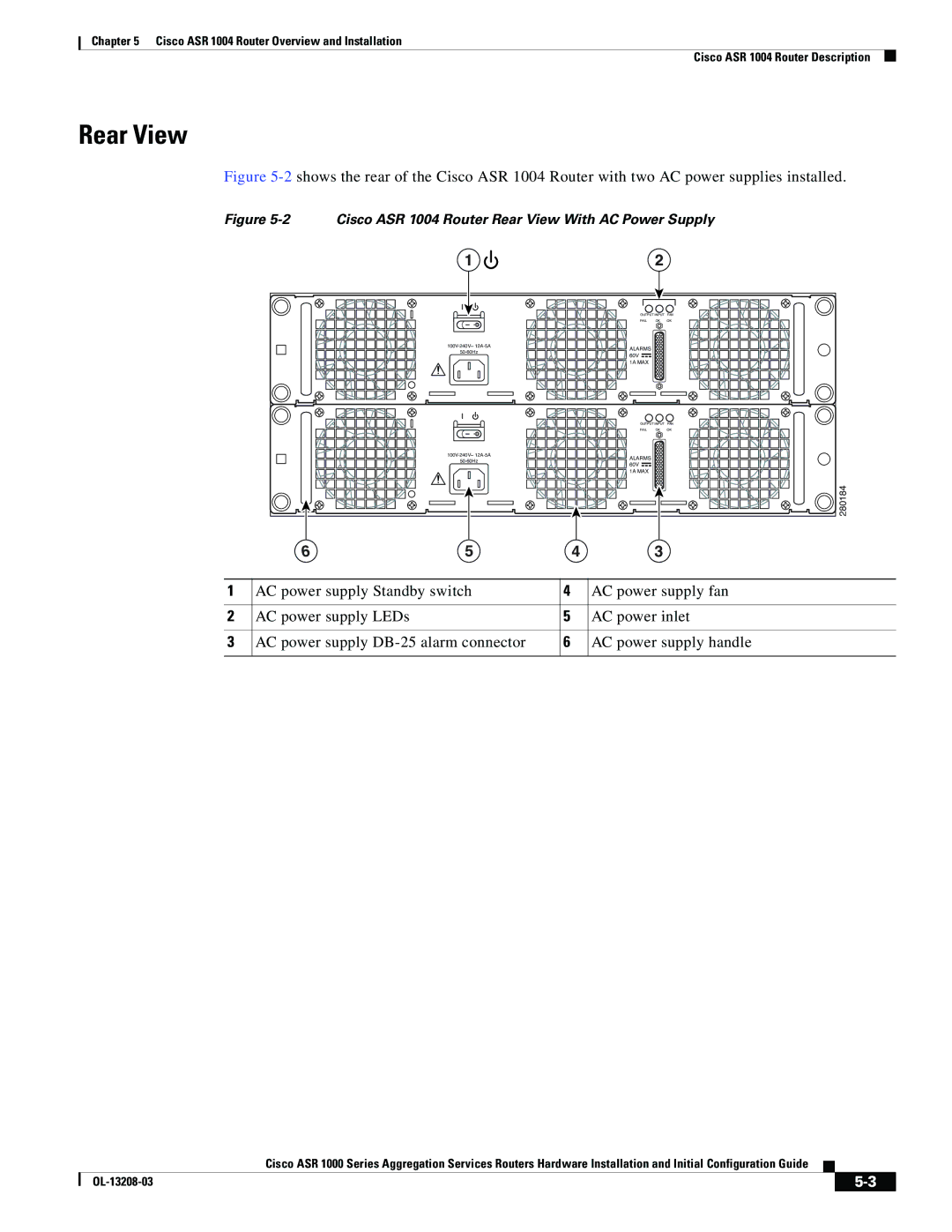
Figure 5-2 shows the rear of the Cisco ASR 1004 Router with two AC power supplies installed.
Figure 5-2 Cisco ASR 1004 Router Rear View With AC Power Supply
1 |
| 2 |
|
| OUTPUT INPUT FAN | ||
| FAIL | OK | OK |
ALARMS |
|
| |
|
| ||
60V |
|
| |
|
|
| |
| 1A MAX |
|
|
| OUTPUT INPUT FAN | ||
| FAIL | OK | OK |
ALARMS |
|
| |
|
| ||
60V |
|
| |
|
|
| |
| 1A MAX |
|
|
|
|
| 280184 |
5 | 4 | 3 |
|
1 | AC power supply Standby switch | 4 | AC power supply fan |
|
|
|
|
2 | AC power supply LEDs | 5 | AC power inlet |
|
|
|
|
3 | AC power supply | 6 | AC power supply handle |
|
|
|
|
Cisco ASR 1000 Series Aggregation Services Routers Hardware Installation and Initial Configuration Guide
|
| ||
|
|