Chapter 2 Cisco ASR 1000 Series Routers Components
Cisco ASR 1000 Series Router Power Supplies
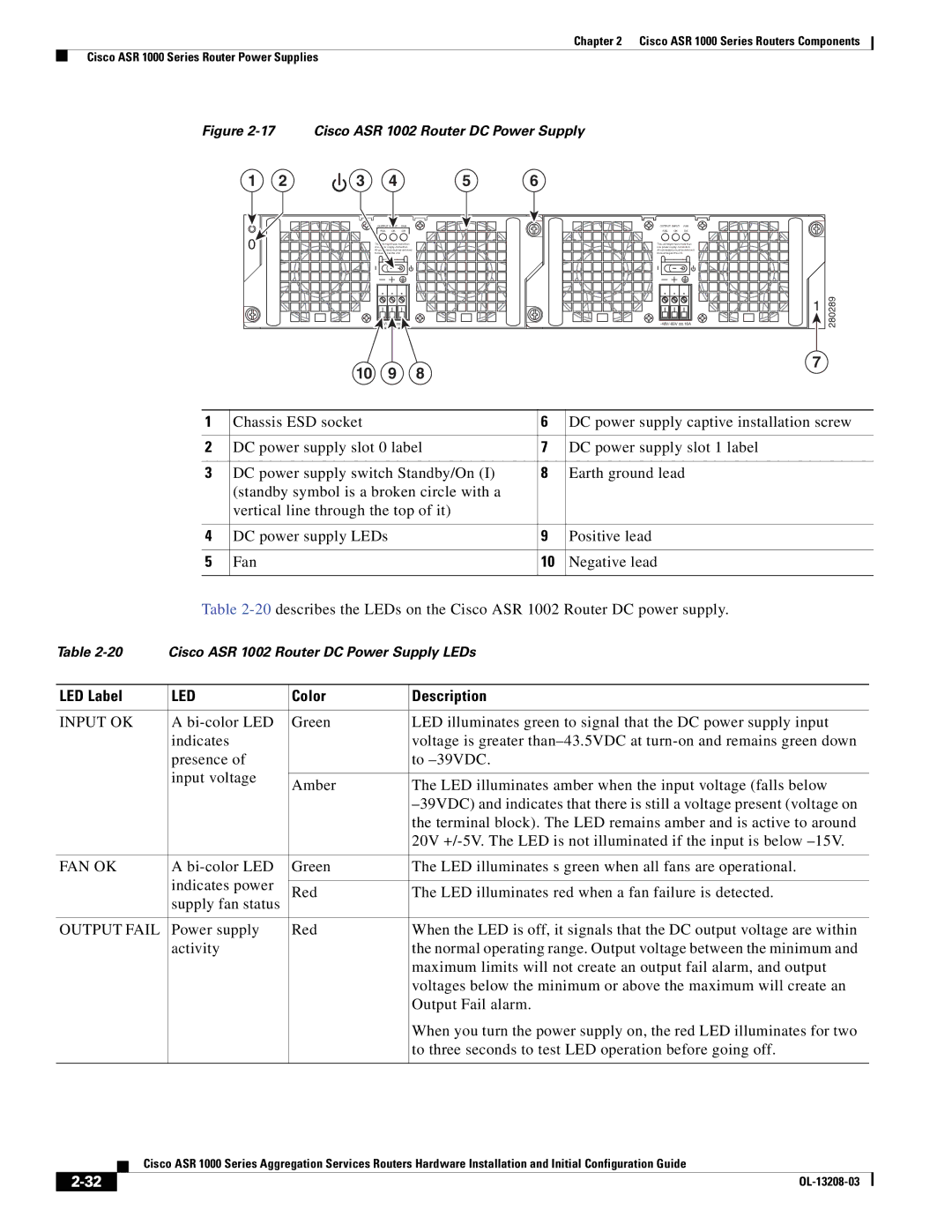
Figure 2-17 Cisco ASR 1002 Router DC Power Supply
1 | 2 | 3 | 4 |
| 5 | 6 |
|
|
| OUTPUT |
| FAN |
| OUTPUT INPUT FAN | |
|
| FAIL | OK | OK |
| FAIL OK | OK |
0 | This unit might have more than | This unit might have more than |
one power supply connection. | one power supply connection. | |
All connections must be removed | All connections must be removed | |
| to | to |
|
|
| 1 | 280289 |
| - |
| ||
|
|
|
| |
10 | 9 | 8 | 7 |
|
|
|
1 | Chassis ESD socket | 6 | DC power supply captive installation screw |
|
|
|
|
2 | DC power supply slot 0 label | 7 | DC power supply slot 1 label |
|
|
|
|
3 | DC power supply switch Standby/On (I) | 8 | Earth ground lead |
| (standby symbol is a broken circle with a |
|
|
| vertical line through the top of it) |
|
|
|
|
|
|
4 | DC power supply LEDs | 9 | Positive lead |
|
|
|
|
5 | Fan | 10 | Negative lead |
|
|
|
|
Table
Table | Cisco ASR 1002 Router DC Power Supply LEDs | ||
|
|
|
|
LED Label | LED | Color | Description |
|
|
|
|
INPUT OK | A | Green | LED illuminates green to signal that the DC power supply input |
| indicates |
| voltage is greater |
| presence of |
| to |
| input voltage |
|
|
| Amber | The LED illuminates amber when the input voltage (falls below | |
|
| ||
|
|
| |
|
|
| the terminal block). The LED remains amber and is active to around |
|
|
| 20V |
|
|
|
|
FAN OK | A | Green | The LED illuminates s green when all fans are operational. |
| indicates power |
|
|
| Red | The LED illuminates red when a fan failure is detected. | |
| supply fan status | ||
|
|
| |
|
|
|
|
OUTPUT FAIL | Power supply | Red | When the LED is off, it signals that the DC output voltage are within |
| activity |
| the normal operating range. Output voltage between the minimum and |
|
|
| maximum limits will not create an output fail alarm, and output |
|
|
| voltages below the minimum or above the maximum will create an |
|
|
| Output Fail alarm. |
|
|
| When you turn the power supply on, the red LED illuminates for two |
|
|
| to three seconds to test LED operation before going off. |
|
|
|
|
Cisco ASR 1000 Series Aggregation Services Routers Hardware Installation and Initial Configuration Guide
|
| |
|