Chapter 6 Cisco ASR 1002 Router Overview and Installation
Connecting Power to Cisco ASR 1002 Router
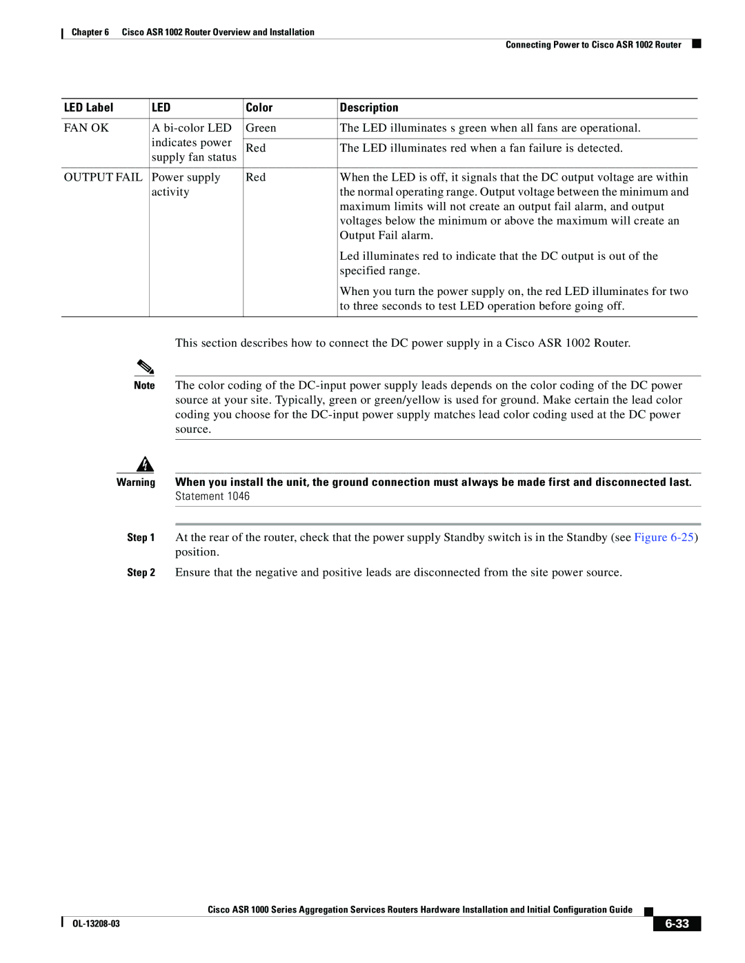
LED Label | LED | Color | Description |
|
|
|
|
FAN OK | A | Green | The LED illuminates s green when all fans are operational. |
| indicates power |
|
|
| Red | The LED illuminates red when a fan failure is detected. | |
| supply fan status | ||
|
|
| |
|
|
|
|
OUTPUT FAIL | Power supply | Red | When the LED is off, it signals that the DC output voltage are within |
| activity |
| the normal operating range. Output voltage between the minimum and |
|
|
| maximum limits will not create an output fail alarm, and output |
|
|
| voltages below the minimum or above the maximum will create an |
|
|
| Output Fail alarm. |
|
|
| Led illuminates red to indicate that the DC output is out of the |
|
|
| specified range. |
|
|
| When you turn the power supply on, the red LED illuminates for two |
|
|
| to three seconds to test LED operation before going off. |
|
|
|
|
This section describes how to connect the DC power supply in a Cisco ASR 1002 Router.
Note The color coding of the
Warning When you install the unit, the ground connection must always be made first and disconnected last.
Statement 1046
Step 1 At the rear of the router, check that the power supply Standby switch is in the Standby (see Figure
Step 2 Ensure that the negative and positive leads are disconnected from the site power source.
|
| Cisco ASR 1000 Series Aggregation Services Routers Hardware Installation and Initial Configuration Guide |
|
| |
|
|
| |||
|
|
|
|
| |
|
|
|
| ||
