Chapter 6 Cisco ASR 1002 Router Overview and Installation
Attaching a Chassis Ground Connection
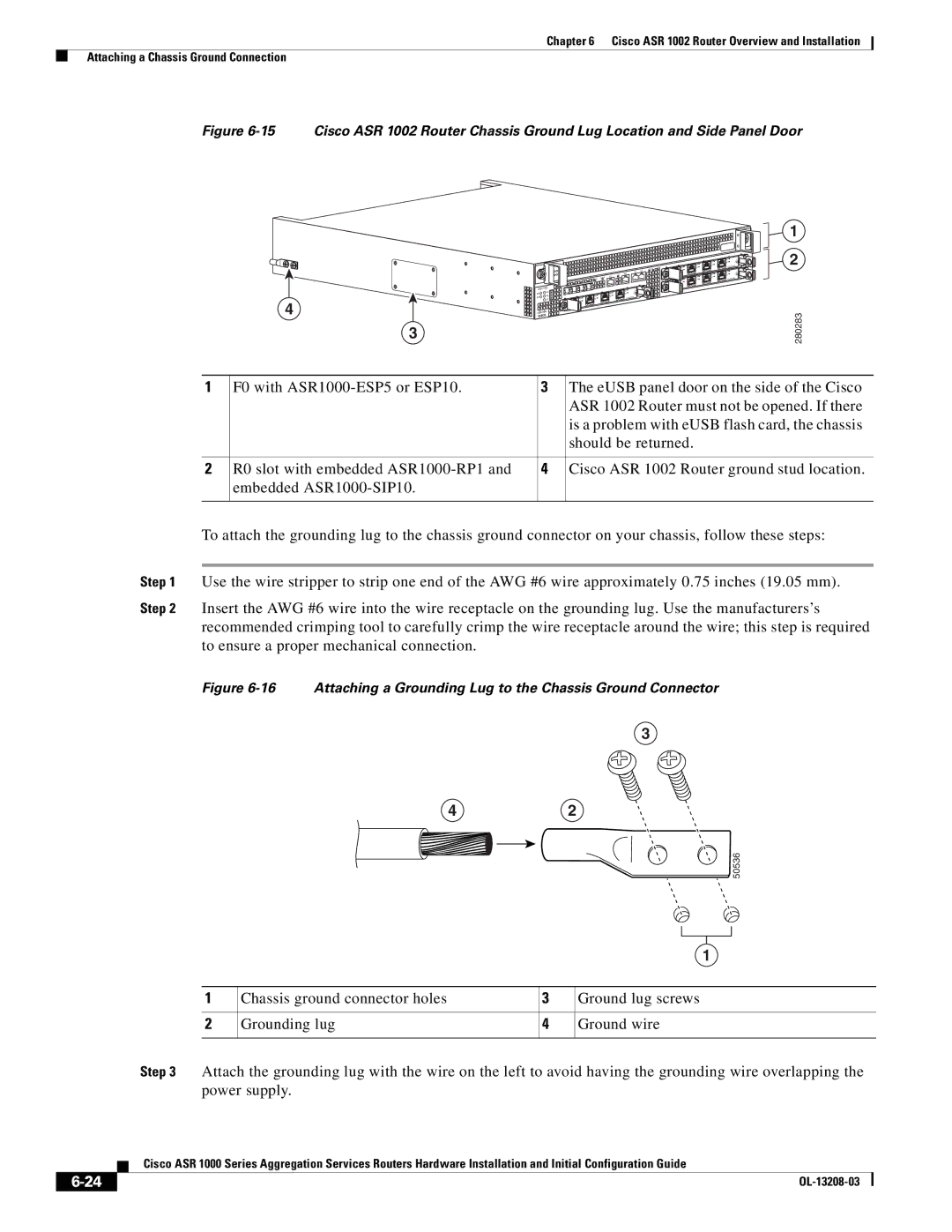
Figure 6-15 Cisco ASR 1002 Router Chassis Ground Lug Location and Side Panel Door
4![]()
3
ASR 1002 | |
stat | min |
pwr | maj |
| crit |
![]() STAT
STAT
![]()
![]()
![]()
![]()
![]()
1
2
280283
1 | F0 with | 3 | The eUSB panel door on the side of the Cisco |
|
|
| ASR 1002 Router must not be opened. If there |
|
|
| is a problem with eUSB flash card, the chassis |
|
|
| should be returned. |
|
|
|
|
2 | R0 slot with embedded | 4 | Cisco ASR 1002 Router ground stud location. |
| embedded |
|
|
|
|
|
|
To attach the grounding lug to the chassis ground connector on your chassis, follow these steps:
Step 1 Use the wire stripper to strip one end of the AWG #6 wire approximately 0.75 inches (19.05 mm).
Step 2 Insert the AWG #6 wire into the wire receptacle on the grounding lug. Use the manufacturers’s recommended crimping tool to carefully crimp the wire receptacle around the wire; this step is required to ensure a proper mechanical connection.
Figure 6-16 Attaching a Grounding Lug to the Chassis Ground Connector
3
42
![]()
![]()
![]() 50536
50536
1
1 | Chassis ground connector holes | 3 | Ground lug screws |
|
|
|
|
2 | Grounding lug | 4 | Ground wire |
|
|
|
|
Step 3 Attach the grounding lug with the wire on the left to avoid having the grounding wire overlapping the power supply.
| Cisco ASR 1000 Series Aggregation Services Routers Hardware Installation and Initial Configuration Guide |
|