Chapter 5 Cisco ASR 1004 Router Overview and Installation
Attaching a Chassis Ground Connection
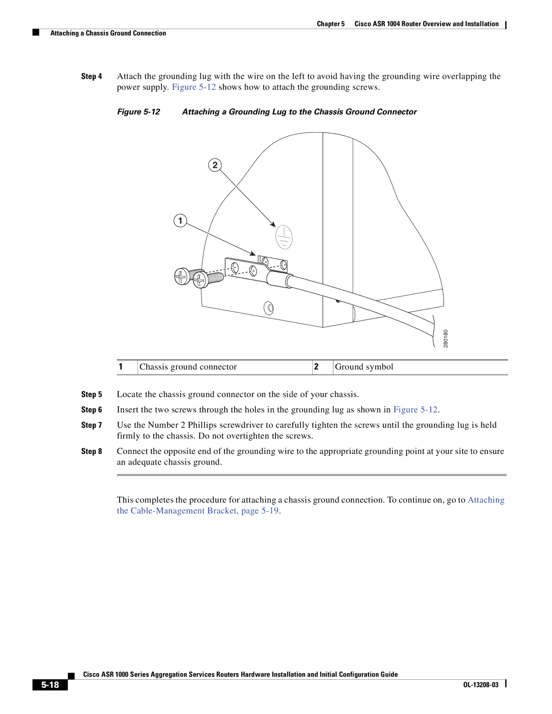
Step 4 Attach the grounding lug with the wire on the left to avoid having the grounding wire overlapping the power supply. Figure
Figure 5-12 Attaching a Grounding Lug to the Chassis Ground Connector
2
1
 280180
1
Chassis ground connector
2
Ground symbol
Step 5 Locate the chassis ground connector on the side of your chassis.
Step 6 Insert the two screws through the holes in the grounding lug as shown in Figure
Step 7 Use the Number 2 Phillips screwdriver to carefully tighten the screws until the grounding lug is held firmly to the chassis. Do not overtighten the screws.
Step 8 Connect the opposite end of the grounding wire to the appropriate grounding point at your site to ensure an adequate chassis ground.
This completes the procedure for attaching a chassis ground connection. To continue on, go to Attaching the
| Cisco ASR 1000 Series Aggregation Services Routers Hardware Installation and Initial Configuration Guide |
|