Chapter 1 Cisco ASR 1000 Series Routers Hardware Overview
Functional Overview
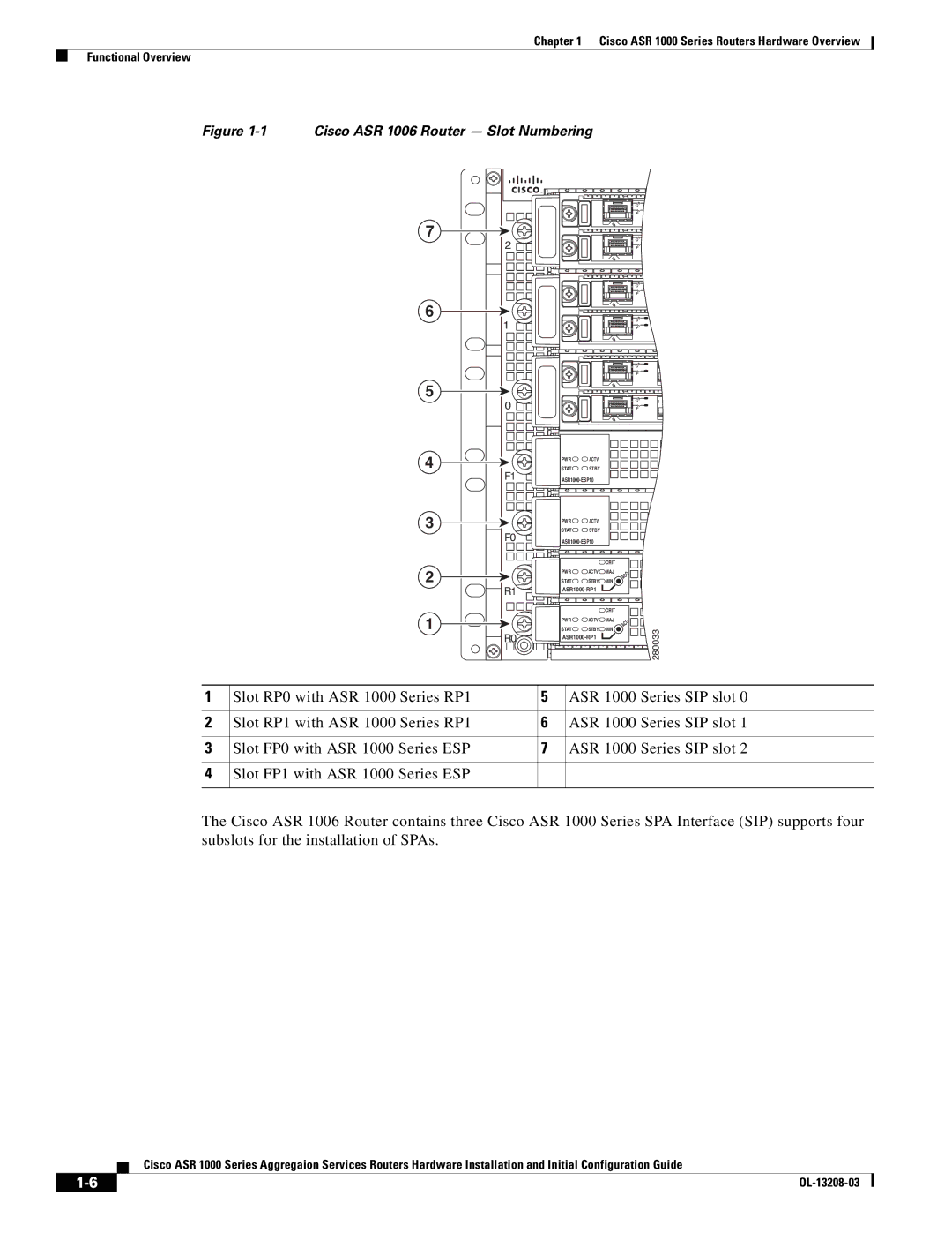
Figure 1-1 Cisco ASR 1006 Router — Slot Numbering
7
6
5
2![]()
![]()
![]()
![]()
1![]()
![]()
![]()
![]()
0![]()
![]()
![]()
![]()
C/A ![]()
A/L ![]()
0
C/A ![]()
A/L ![]()
0
C/A ![]()
A/L ![]()
0
C/A ![]()
A/L ![]()
0
C/A ![]()
A/L ![]()
0
C/A ![]()
A/L ![]()
0
4
F1
3 |
F0 |
2 |
R1 |
1
![]() R0
R0![]()
PWR![]()
![]() ACTV
ACTV
STAT![]()
![]() STBY
STBY
PWR![]()
![]() ACTV
ACTV
STAT![]()
![]() STBY
STBY
|
| CRIT |
|
| |
PWR | ACTV | MAJ | ACO | ||
STAT | STBY | MIN | |||
|
| ||||
|
|
| |||
|
| CRIT |
|
| |
PWR | ACTV | MAJ |
| O | |
|
|
|
| ||
|
|
| C | ||
STAT | STBY | MIN | A |
| |
|
| ||||
![]()
![]()
![]()
![]() 280033
280033
1 | Slot RP0 with ASR 1000 Series RP1 | 5 | ASR 1000 Series SIP slot 0 |
|
|
|
|
2 | Slot RP1 with ASR 1000 Series RP1 | 6 | ASR 1000 Series SIP slot 1 |
|
|
|
|
3 | Slot FP0 with ASR 1000 Series ESP | 7 | ASR 1000 Series SIP slot 2 |
|
|
|
|
4 | Slot FP1 with ASR 1000 Series ESP |
|
|
|
|
|
|
The Cisco ASR 1006 Router contains three Cisco ASR 1000 Series SPA Interface (SIP) supports four subslots for the installation of SPAs.
Cisco ASR 1000 Series Aggregaion Services Routers Hardware Installation and Initial Configuration Guide
|
| |
|