Chapter 4 Cisco ASR 1006 Router Overview and Installation
Connecting Power to Cisco ASR 1006 Router
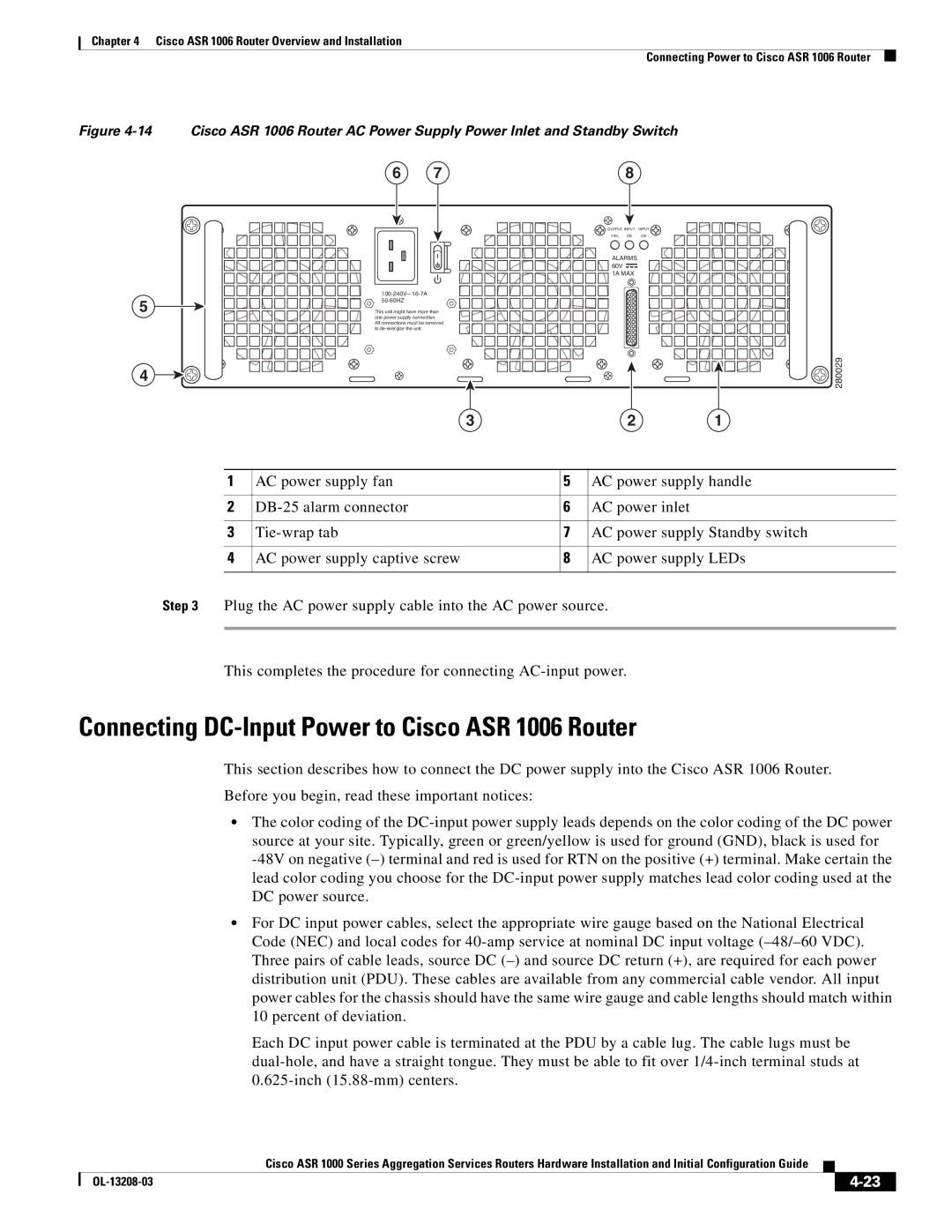
Figure
5
4
Cisco ASR 1006 Router AC Power Supply Power Inlet and Standby Switch
6 | 7 | 8 |
| OUTPUT INPUT INPUT | |
| FAIL | OK OK |
ALARMS 


 60V
60V 


 1A MAX
This unit might have more than one power supply connection. All connections must be removed to
3 | 2 | 1 |
280029
1 | AC power supply fan | 5 | AC power supply handle |
|
|
|
|
2 | 6 | AC power inlet | |
|
|
|
|
3 | 7 | AC power supply Standby switch | |
|
|
|
|
4 | AC power supply captive screw | 8 | AC power supply LEDs |
|
|
|
|
Step 3 Plug the AC power supply cable into the AC power source.
This completes the procedure for connecting
Connecting DC-Input Power to Cisco ASR 1006 Router
This section describes how to connect the DC power supply into the Cisco ASR 1006 Router.
Before you begin, read these important notices:
•The color coding of the
•For DC input power cables, select the appropriate wire gauge based on the National Electrical Code (NEC) and local codes for
Each DC input power cable is terminated at the PDU by a cable lug. The cable lugs must be
|
| Cisco ASR 1000 Series Aggregation Services Routers Hardware Installation and Initial Configuration Guide |
|
| |
|
|
| |||
|
|
|
| ||
|
|
|
| ||
