Chapter 8 Replacing Cisco ASR 1000 Series Routers
Removing and Replacing a Cisco ASR 1006 Router Power Supply
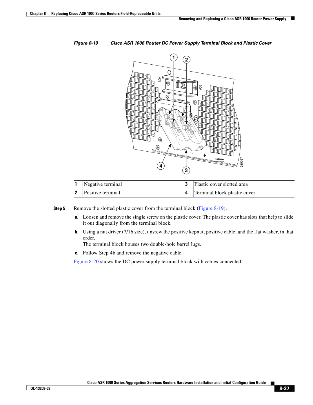
Figure 8-19 Cisco ASR 1006 Router DC Power Supply Terminal Block and Plastic Cover
1 2
![]()
![]() OFF
OFF
55
-
| 40A |
|
This |
|
|
|
unit |
|
|
|
might | e more | one |
|
| supply | ||
|
| ||
|
|
|
4
3
. All connections must be remov
280027
1 | Negative terminal | 3 | Plastic cover slotted area |
|
|
|
|
2 | Positive terminal | 4 | Terminal block plastic cover |
|
|
|
|
Step 5 Remove the slotted plastic cover from the terminal block (Figure
a.Loosen and remove the single screw on the plastic cover. The plastic cover has slots that help to slide it out diagonally from the terminal block.
b.Using a nut driver (7/16 size), unsrew the positive kepnut, positive cable, and the flat washer, in that order.
The terminal block houses two
c.Follow Step 4b and remove the negative cable.
Figure 8-20 shows the DC power supply terminal block with cables connected.
|
| Cisco ASR 1000 Series Aggregation Services Routers Hardware Installation and Initial Configuration Guide |
|
| |
|
|
| |||
|
|
|
|
| |
|
|
|
| ||
