Chapter 6 Cisco ASR 1002 Router Overview and Installation
Connecting a Terminal to the Cisco
Step 7 Connect the ground, positive, and negative leads to the power source.
Step 8 Turn the branch source breaker on.
Step 9 Place the DC Standby switch in the On (I) position. The power supply LEDs light when power is supplied to the router.
You have completed the procedure for connecting a DC power supply in the Cisco ASR 1002 Router.
Connecting a Terminal to the Cisco ASR1000-RP1 Console Port
The Cisco ASR 1002 embedded router processor has an asynchronous serial
•One
•One
•One
A crossover cable reverses pin connections from one end to the other. In other words, it connects pin 1 (at one end) to pin 8 (at the other end), pin 2 to pin 7, pin 3 to pin 6, and so on. You can identify a crossover cable by comparing the two modular ends of the cable. Hold the cable ends in your hand,
Use the following procedure to connect a video terminal to the console port on a route processor.
Note Each Cisco ASR 1000 Series Route Processor 1 must have a console port connection (typically to a terminal server) if you are running a redundant configuration in the chassis.
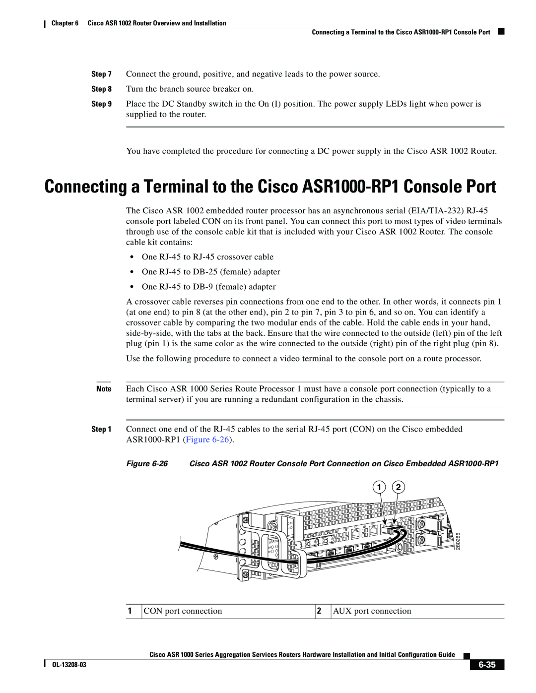
Step 1 Connect one end of the
Figure 6-26 Cisco ASR 1002 Router Console Port Connection on Cisco Embedded ASR1000-RP1
1 2
ASR | 1002 | |
min | ||
stat | ||
maj | ||
pwr | ||
crit | ||
|
![]() STAT
STAT
|
|
|
|
|
| LINK |
|
|
|
| CARRIER | MTS | |
|
| BOOT |
|
| ||
QE2 | QE3 |
|
|
|
| |
QE1 |
|
|
|
|
|
|
QE0 |
|
|
|
|
|
|
|
|
|
|
| C | /A |
|
|
|
|
|
| |
|
| C/ | A |
| A | /L |
C | /A | A | /L |
|
| 3 |
|
|
|
|
| ||
A | /L |
|
| 2 |
|
|
|
|
|
|
| ||
|
| 1 |
|
|
|
|
0 |
|
|
|
|
|
|
MGMT |
|
|
|
| |
C | /A |
|
| U | S |
A/L | S | T AT |
|
| |
|
|
| |||
|
|
|
| ||
PWR STAT CO
C | /A |
A | /L |
0 |
|
C/ | A |
| |
A | /L |
0 |
|
![]() 1
1
![]() 1
1
 280285
1
CON port connection
2
AUX port connection
|
| Cisco ASR 1000 Series Aggregation Services Routers Hardware Installation and Initial Configuration Guide |
|
| |
|
|
| |||
|
|
|
|
| |
|
|
|
| ||
