Chapter 2 Cisco ASR 1000 Series Routers Components
Cisco ASR 1000 Series Router Power Supplies
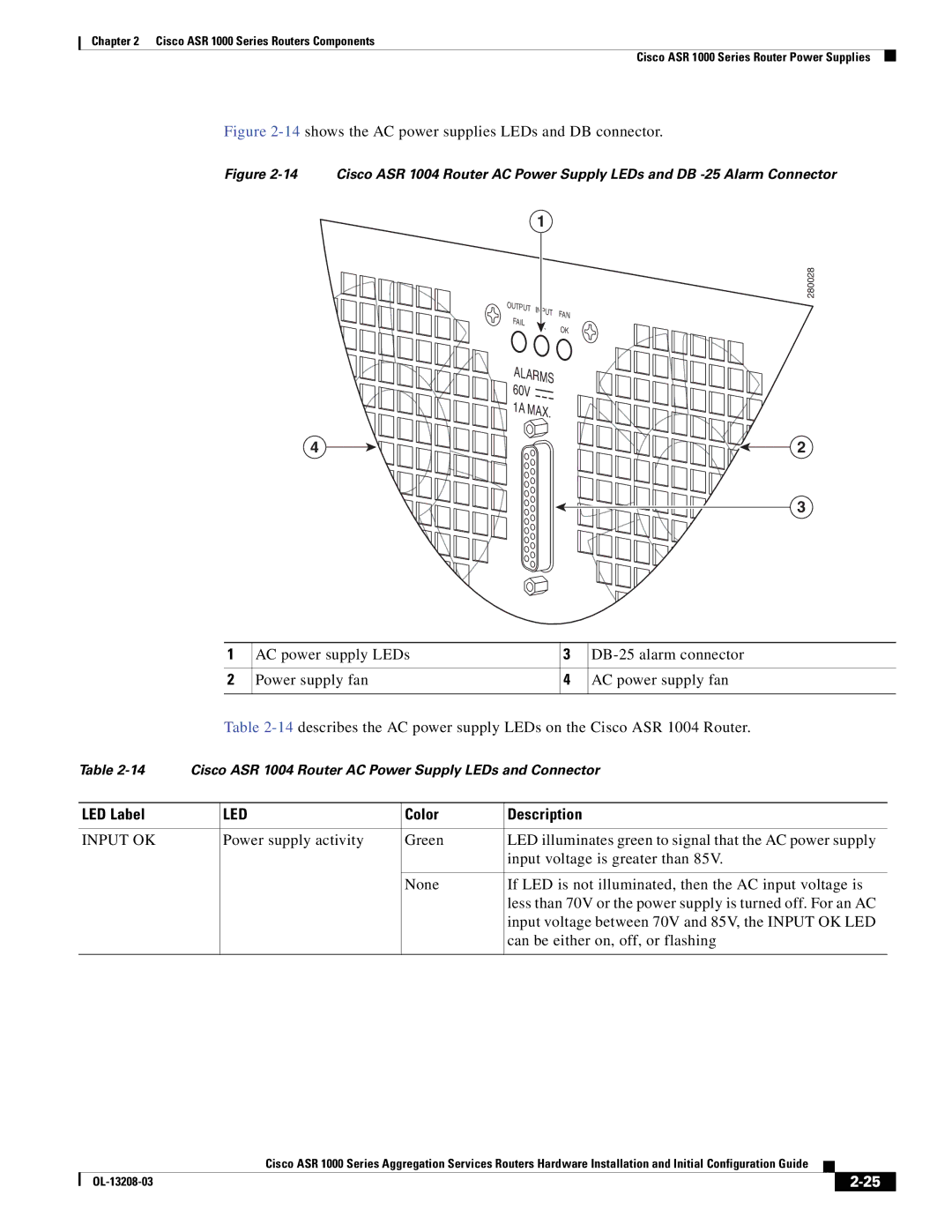
Figure 2-14 shows the AC power supplies LEDs and DB connector.
Figure 2-14 Cisco ASR 1004 Router AC Power Supply LEDs and DB -25 Alarm Connector
1
4![]()
![]()
![]()
![]()
![]()
![]()
![]()
![]()
280028
OUTPUT | INPUT | FAN | |
FAIL | |||
| |||
| OK | ||
|
|
ALARMS 60V ![]()
 1A MAX.


 2
2
![]()
![]()
![]()
![]()
![]()
![]()
![]()
![]()
![]()
![]()
![]()
![]()
![]() 3
3
1 | AC power supply LEDs | 3 | |
|
|
|
|
2 | Power supply fan | 4 | AC power supply fan |
|
|
|
|
Table
Table | Cisco ASR 1004 Router AC Power Supply LEDs and Connector | |||
|
|
|
|
|
LED Label |
| LED | Color | Description |
|
|
|
|
|
INPUT OK |
| Power supply activity | Green | LED illuminates green to signal that the AC power supply |
|
|
|
| input voltage is greater than 85V. |
|
|
|
|
|
|
|
| None | If LED is not illuminated, then the AC input voltage is |
|
|
|
| less than 70V or the power supply is turned off. For an AC |
|
|
|
| input voltage between 70V and 85V, the INPUT OK LED |
|
|
|
| can be either on, off, or flashing |
|
|
|
|
|
|
| Cisco ASR 1000 Series Aggregation Services Routers Hardware Installation and Initial Configuration Guide |
|
| |
|
|
| |||
|
|
|
| ||
|
|
|
| ||
