Chapter 2 Cisco ASR 1000 Series Routers Components
Cisco ASR 1000 Series Router Power Supplies
AC/DC Power System Output for Cisco ASR 1006
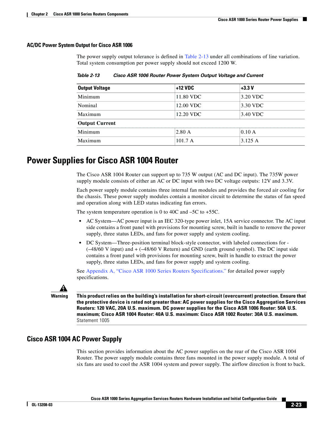
The power supply output tolerance is defined in Table
Table | Cisco ASR 1006 Router Power System Output Voltage and Current | ||||
|
|
|
| ||
Output Voltage |
| +12 VDC | +3.3 V | ||
|
|
|
|
|
|
Minimum |
| 11.80 | VDC | 3.20 | VDC |
|
|
|
|
|
|
Nominal |
| 12.00 | VDC | 3.30 | VDC |
|
|
|
|
|
|
Maximum |
| 12.20 | VDC | 3.40 | VDC |
|
|
|
|
| |
Output Current |
|
|
| ||
|
|
|
|
| |
Minimum |
| 2.80 A | 0.10 | A | |
|
|
|
|
| |
Maximum |
| 101.7 | A | 3.125 A | |
|
|
|
|
|
|
Power Supplies for Cisco ASR 1004 Router
The Cisco ASR 1004 Router can support up to 735 W output (AC and DC input). The 735W power supply module consists of either an AC or DC input with two DC voltage outputs: 12V and 3.3V.
Each power supply module contains three internal fan modules and provides the forced air cooling for the chassis. These power supply modules contain a monitor circuit to determine the status of fan speed and operation along with LED status indicating fan errors.
The system temperature operation is 0 to 40C and
•AC
•DC
See Appendix A, “Cisco ASR 1000 Series Routers Specifications.” for detailed power supply specifications.
Warning This product relies on the building’s installation for
Cisco ASR 1004 AC Power Supply
This section provides information about the AC power supplies on the rear of the Cisco ASR 1004 Router. The power supply module contains three fans mounted in the power supply module. A total of six fans are used to cool the ASR 1004 system and power supply. The airflow direction is front to back.
|
| Cisco ASR 1000 Series Aggregation Services Routers Hardware Installation and Initial Configuration Guide |
|
| |
|
|
| |||
|
|
|
| ||
|
|
|
| ||
