Chapter 5 Cisco ASR 1004 Router Overview and Installation
Attaching a Chassis Ground Connection
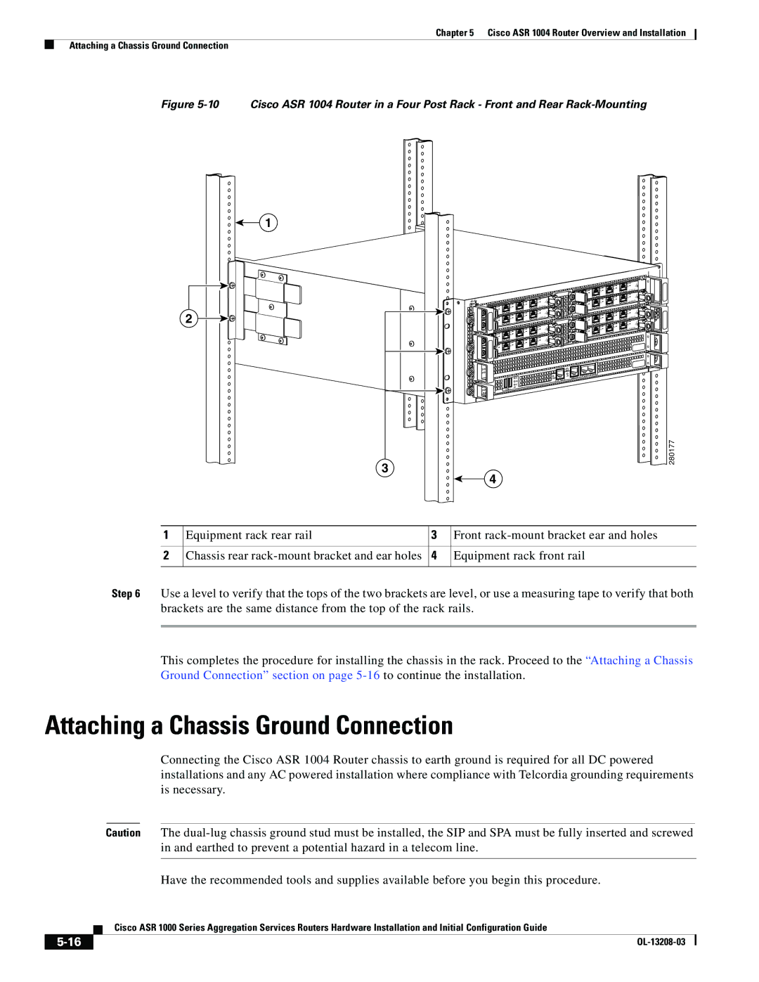
Figure 5-10 Cisco ASR 1004 Router in a Four Post Rack - Front and Rear Rack-Mounting
1
2
| 1 |
| 0 |
| |
3 | 1 |
2 | 0 |
1 |
|
0 | |
| |
3 |
|
2 |
|
1 | 1 |
0 | 0 |
| |
3 | 1 |
2 | 0 |
1 |
|
0 | |
| |
3 |
|
2 |
|
1 |
|
0 |
|
|
|
|
|
|
|
| LINK | AUX |
|
|
|
|
|
|
| CON | |
|
|
|
| HD | CARRIE | R | BITS | MGMT ETHERNET |
|
| CRIT |
| USB |
|
|
|
|
| ACTV | MAJ |
| DF |
|
|
|
|
PWR |
|
| DISK |
|
|
|
| |
STAT | STBY | MIN | 0 | 1 |
|
|
|
|
|
|
|
|
|
|
| ||
![]()
![]() SPA-4XOC3-POS
SPA-4XOC3-POS![]()
![]()
![]()
![]()
![]() 3
3 ![]()
![]() 2
2 ![]()
![]()
![]()
![]()
![]()
![]()
![]()
![]()
![]()
![]()
![]() SPA-4XOC3-POS
SPA-4XOC3-POS![]() 3 2
3 2![]()
![]()
![]()
![]() SPA-4XOC3-POS
SPA-4XOC3-POS![]()
![]() 3
3 ![]()
![]()
![]() 2
2 ![]()
![]()
![]()
![]()
![]()
![]()
![]()
![]() SPA-4XOC3-POS
SPA-4XOC3-POS![]()
![]()
![]() 3
3![]() 2
2
3
280177
4
1 | Equipment rack rear rail | 3 | Front |
|
|
|
|
2 | Chassis rear | 4 | Equipment rack front rail |
|
|
|
|
Step 6 Use a level to verify that the tops of the two brackets are level, or use a measuring tape to verify that both brackets are the same distance from the top of the rack rails.
This completes the procedure for installing the chassis in the rack. Proceed to the “Attaching a Chassis Ground Connection” section on page
Attaching a Chassis Ground Connection
Connecting the Cisco ASR 1004 Router chassis to earth ground is required for all DC powered installations and any AC powered installation where compliance with Telcordia grounding requirements is necessary.
Caution The
Have the recommended tools and supplies available before you begin this procedure.
| Cisco ASR 1000 Series Aggregation Services Routers Hardware Installation and Initial Configuration Guide |
|
