Chapter 2 Cisco ASR 1000 Series Routers Components
Cisco ASR 1000 Series Router Power Supplies
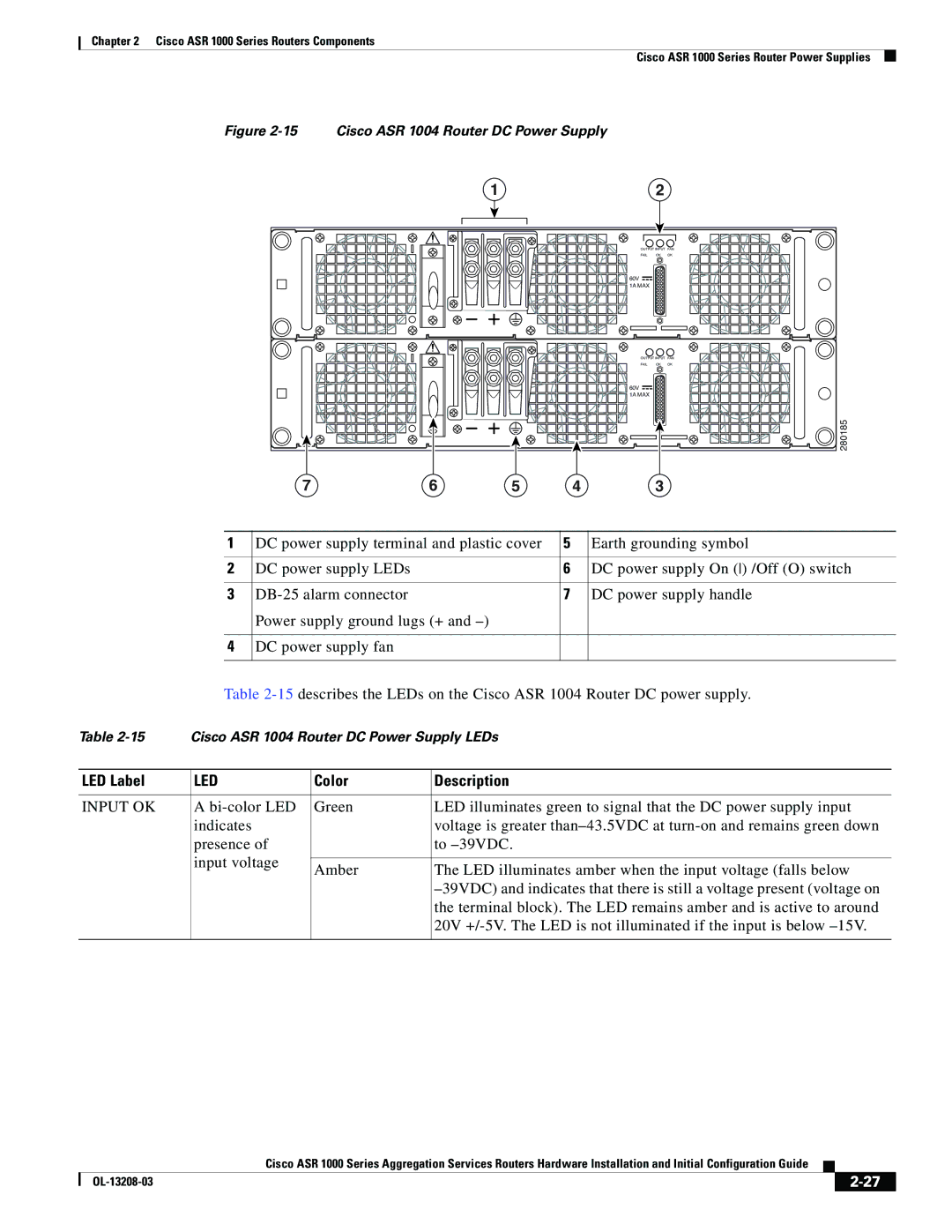
Figure 2-15 Cisco ASR 1004 Router DC Power Supply
|
| 1 |
| 2 |
|
|
|
| OUTPUT INPUT FAN | ||
|
|
| FAIL | OK | OK |
|
|
| 60V |
|
|
|
|
| 1A MAX |
|
|
|
|
| OUTPUT INPUT FAN | ||
|
|
| FAIL | OK | OK |
|
|
| 60V |
|
|
|
|
| 1A MAX |
|
|
|
|
|
|
| 280185 |
7 | 6 | 5 | 4 | 3 |
|
1 | DC power supply terminal and plastic cover | 5 | Earth grounding symbol |
|
|
|
|
2 | DC power supply LEDs | 6 | DC power supply On () /Off (O) switch |
|
|
|
|
3 | 7 | DC power supply handle | |
| Power supply ground lugs (+ and |
|
|
|
|
|
|
4 | DC power supply fan |
|
|
|
|
|
|
Table
Table | Cisco ASR 1004 Router DC Power Supply LEDs | ||
|
|
|
|
LED Label | LED | Color | Description |
|
|
|
|
INPUT OK | A | Green | LED illuminates green to signal that the DC power supply input |
| indicates |
| voltage is greater |
| presence of |
| to |
| input voltage |
|
|
| Amber | The LED illuminates amber when the input voltage (falls below | |
|
| ||
|
|
| |
|
|
| the terminal block). The LED remains amber and is active to around |
|
|
| 20V |
|
|
|
|
Cisco ASR 1000 Series Aggregation Services Routers Hardware Installation and Initial Configuration Guide
|
| ||
|
|