Chapter 4 Cisco ASR 1006 Router Overview and Installation
Connecting System Cables
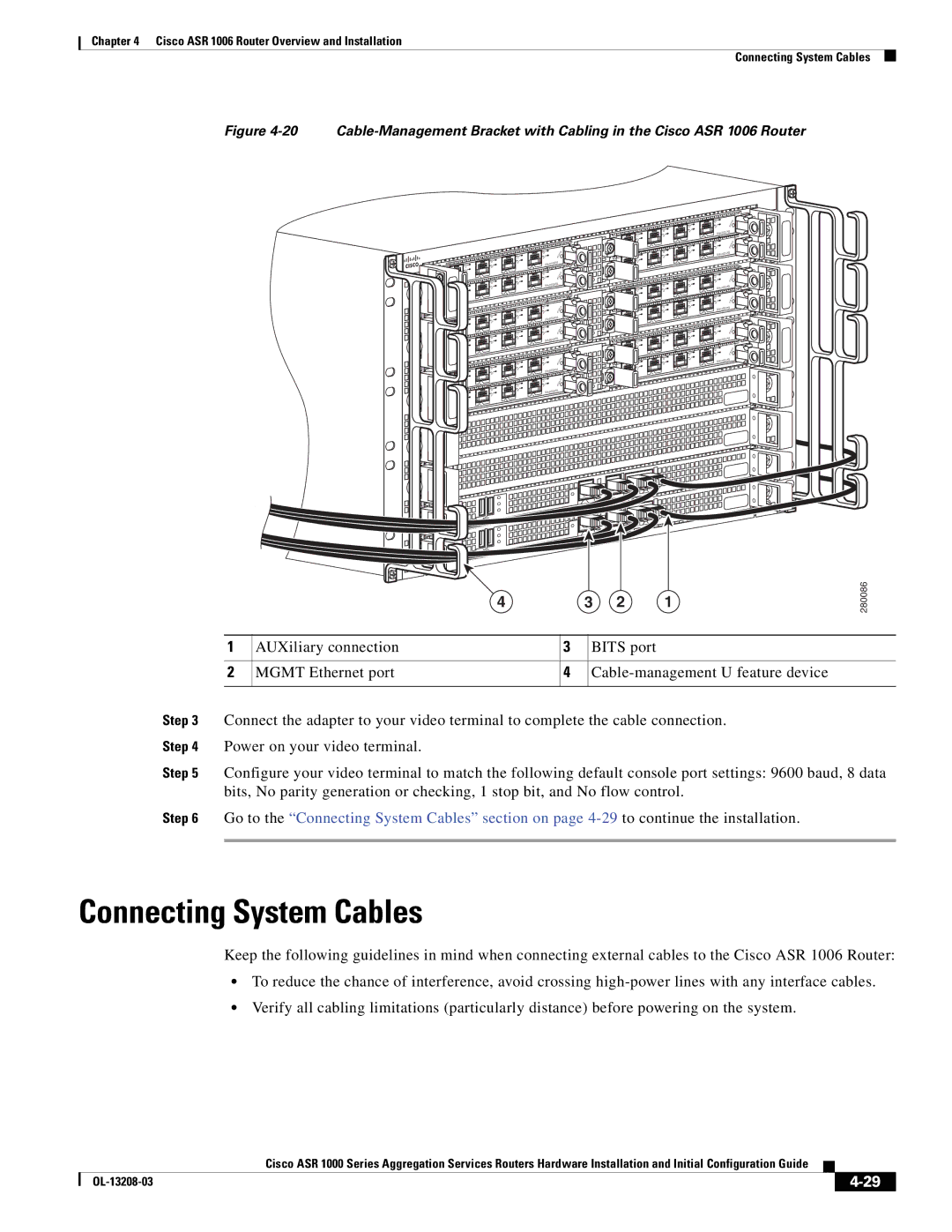
Figure 4-20 Cable-Management Bracket with Cabling in the Cisco ASR 1006 Router
|
|
|
| C | /A |
|
| C | /A | A | /L |
C | /A | A/L |
| 3 | |
|
| ||||
A/L |
|
| 2 |
| |
|
| 1 |
| C | /A |
0 |
| C | /A | A/L | |
|
|
| |||
C | /A | A | /L |
| 3 |
A | /L |
|
| 2 |
|
|
| 1 |
|
|
|
0 |
|
|
|
|
|
|
|
|
| C/A | |
|
| C | /A | A/ | L |
|
|
|
| ||
C | /A | A/L |
| 3 | |
|
| ||||
A | /L |
|
| 2 |
|
|
| 1 |
| C | /A |
0 |
| C | /A | A/L | |
|
|
| |||
C/ | A | A/L |
|
| |
|
| 3 | |||
A/L |
|
| 2 |
| |
|
| 1 |
|
|
|
0 |
|
|
|
|
|
|
|
|
| C | /A |
|
| C | /A | A/L | |
C | /A | A/ | L |
| 3 |
|
|
| |||
A/L |
|
| 2 |
| |
|
| 1 |
| C/A | |
0 |
| C | /A | A | /L |
C | /A | A/L |
| 3 | |
|
| ||||
A | /L |
|
| 2 |
|
|
|
|
| ||
|
| 1 |
|
|
|
0 |
|
|
|
|
|
C | /A |
| TU | S |
| TA |
| ||
A/ | L |
|
| |
| S |
|
|
|
|
|
|
| ||
C | /A |
|
| TAT | U | S |
A/ | L |
| S |
|
| |
|
|
|
|
| ||
|
|
|
|
| ||
C | /A |
|
|
| TU | S |
|
|
| TA |
| ||
A/L |
| S |
|
| ||
|
|
|
| |||
|
|
|
|
| ||
C | /A |
|
| TAT | U | S |
A/ | L |
| S |
|
| |
|
|
|
|
| ||
|
|
|
|
| ||
C | /A |
|
| T | U | S |
| /L |
| S | T A |
|
|
A |
|
|
|
| ||
|
|
|
|
| ||
|
|
|
|
|
| |
C | /A |
|
|
| US | |
|
|
| T | |||
A/L |
| S | T A |
|
| |
|
|
|
| |||
|
|
|
|
| ||
|
|
|
|
|
| |
C /A![]()
A/L
| 1 |
0 |
|
C | /A |
A | /L |
| 1 |
0 |
|
C | /A |
A/L | |
| 1 |
0 |
|
C | /A |
A/ | L |
| |
| 1 |
0 |
|
C/A | |
A | /L |
| 1 |
0 |
|
C/A | |
A | /L |
| 1 |
0 |
|
| C | /A |
C | /A | /L |
A | ||
A | /L |
|
|
| 2 |
|
|
| C/A | |
C | /A | A | /L |
A/L
![]() 2
2
C/A![]()
C | /A | A | /L |
A/L
![]() 2
2
C/A![]()
C | /A | A/L |
| ||
A/L |
| |
|
| 2 |
|
| C/A |
C | /A | A /L |
A/L
|
| 2 |
|
|
| C | /A |
C | /A | A | /L |
|
A/L
![]() 2
2
C | /A |
| TU | S |
| TA |
| ||
A | /L | S |
|
|
|
|
|
|
| ||
|
|
|
|
|
| |
3 |
|
|
|
|
|
|
C | /A |
| STAT | U | S | |
A | /L |
|
|
| ||
|
|
|
|
| ||
|
|
|
|
|
| |
3 |
|
|
|
|
|
|
C | /A |
|
| T AT | U | S |
| /L |
| S |
|
| |
A |
|
|
|
| ||
|
|
|
|
| ||
|
|
|
|
|
| |
3 |
|
|
|
|
|
|
C/A |
|
| TAT | U | S | |
A | /L |
| S |
|
| |
|
|
|
|
| ||
|
|
|
|
|
| |
3 |
|
|
|
|
|
|
C | /A |
|
| TAT | U | S |
A | /L |
| S |
|
| |
|
|
|
|
| ||
3 |
|
|
|
|
|
|
C | /A |
|
| T AT | U | S |
| /L |
| S |
|
| |
A |
|
|
|
| ||
|
|
|
|
| ||
3 |
|
|
|
|
|
|
4 | 3 | 2 | 1 |
280086
| 1 | AUXiliary connection | 3 | BITS port |
|
|
|
|
|
| 2 | MGMT Ethernet port | 4 | |
|
|
|
|
|
Step 3 | Connect the adapter to your video terminal to complete the cable connection. | |||
Step 4 | Power on your video terminal. |
|
| |
Step 5 | Configure your video terminal to match the following default console port settings: 9600 baud, 8 data | |||
| bits, No parity generation or checking, 1 stop bit, and No flow control. | |||
Step 6 | Go to the “Connecting System Cables” section on page | |||
|
|
|
|
|
Connecting System Cables
Keep the following guidelines in mind when connecting external cables to the Cisco ASR 1006 Router:
•To reduce the chance of interference, avoid crossing
•Verify all cabling limitations (particularly distance) before powering on the system.
|
| Cisco ASR 1000 Series Aggregation Services Routers Hardware Installation and Initial Configuration Guide |
|
| |
|
|
| |||
|
|
|
| ||
|
|
|
| ||