Chapter 5 Cisco ASR 1004 Router Overview and Installation
Connecting Shared Port Adapter Cables
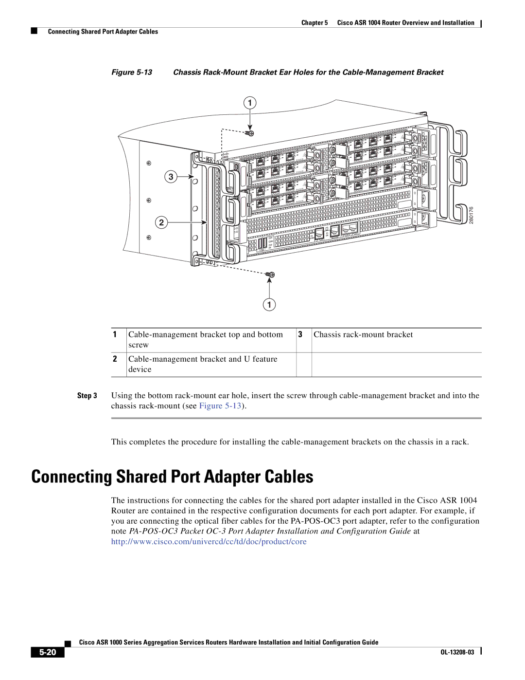
Figure 5-13 Chassis Rack-Mount Bracket Ear Holes for the Cable-Management Bracket
1
3
|
|
|
| C/ | A |
|
| C/ | A | A/ | L |
C/A |
| 3 | |||
A | /L |
| |||
A | /L |
|
| 2 |
|
|
| 1 |
| C/A | |
0 |
| C/ | A | A/L | |
|
|
| |||
C/ | A | A/L |
|
| |
|
| 3 | |||
A | /L |
|
| 2 |
|
|
|
|
| ||
|
| 1 |
|
|
|
0 |
|
|
|
|
|
|
|
|
| C/A | |
|
| C/ | A | A/L | |
C/A | A/ | L |
| 3 | |
A | /L |
|
| 2 |
|
|
| 1 |
| C/ | A |
|
|
|
|
| |
0 |
| C/ | A | A/ | L |
C/ | A | A | /L |
| 3 |
|
|
| |||
A | /L |
|
| 2 |
|
|
|
|
| ||
|
| 1 |
|
|
|
0 |
|
|
|
|
|
C/A |
| TATUS | |||
A/L | S | ||||
|
| ||||
|
|
|
| ||
C/A |
| T AT | US | ||
A/L | S |
| |||
|
| ||||
|
|
|
| ||
C/ | A |
| TATUS | ||
|
| ||||
A | /L | S |
|
| |
|
|
|
| ||
C/ | A |
|
| US | |
|
| T AT | |||
| /L | S |
| ||
A |
|
| |||
|
|
|
| ||
|
|
|
| C/A | |
|
| C/ | A | A/L | |
|
|
| |||
C/ | A |
| /L |
|
|
| A |
|
| ||
A | /L |
|
| 2 |
|
|
|
|
| ||
|
| 1 |
| C/A | |
0 |
| C | /A | A/L | |
|
|
| |||
C | /A | A | /L |
|
|
|
|
| |||
A | /L |
|
| 2 |
|
|
|
|
| ||
|
| 1 |
|
|
|
0 |
|
|
|
|
|
|
| C/A | C/A | ||
|
| A/ | L | ||
C/ | A | A/L |
|
| |
|
|
| |||
A | /L |
|
| 2 |
|
|
|
|
| ||
|
| 1 |
| C/A | |
|
|
|
| ||
0 |
| C/A | A/ | L | |
|
|
| |||
C/ | A |
| /L |
|
|
| A |
|
| ||
A | /L |
|
| 2 |
|
|
|
|
| ||
|
| 1 |
|
|
|
0 |
|
|
|
|
|
C/ | A | TATUS |
| ||
A | /L | S |
|
|
|
|
| |
3 |
|
|
|
|
|
C/ | A |
|
|
| US |
|
|
| AT | ||
A/L | S | T |
| ||
|
|
| |||
|
|
|
|
| |
3 |
|
|
|
|
|
C/ | A |
| TATUS | ||
A/L | S |
|
|
| |
|
|
|
|
| |
3 |
|
|
|
|
|
C/ | A |
|
|
| US |
|
| T A | T | ||
A/L | S |
|
| ||
|
|
| |||
|
|
|
|
| |
3 |
|
|
|
|
|
280176
2
|
|
|
|
|
|
| LINK |
| AUX |
|
|
|
|
|
|
|
| CON | |
|
|
|
|
|
| HD | CARRIER | MGMT | ETHERNET |
|
|
|
|
|
|
| |||
|
|
|
|
|
| USB | BITS |
|
|
|
| CRIT |
|
|
|
|
|
| |
|
|
|
|
| DF |
|
|
| |
| ACTV | MAJ |
| O |
|
|
|
| |
PWR | AC |
| DISK |
|
|
| |||
|
|
|
|
|
| ||||
STBY | MIN |
|
| 0 | 1 |
|
|
| |
STAT |
|
|
|
|
|
| |||
|
|
|
|
|
|
|
| ||
ASR1000 |
|
|
|
|
|
|
|
| |
|
|
|
|
|
|
|
|
|
1
1 | 3 | Chassis | |
| screw |
|
|
|
|
|
|
2 |
|
| |
| device |
|
|
|
|
|
|
Step 3 Using the bottom
This completes the procedure for installing the
Connecting Shared Port Adapter Cables
The instructions for connecting the cables for the shared port adapter installed in the Cisco ASR 1004 Router are contained in the respective configuration documents for each port adapter. For example, if you are connecting the optical fiber cables for the
| Cisco ASR 1000 Series Aggregation Services Routers Hardware Installation and Initial Configuration Guide |
|