Chapter 5 Cisco ASR 1004 Router Overview and Installation
Connecting Power to Cisco ASR 1004 Router
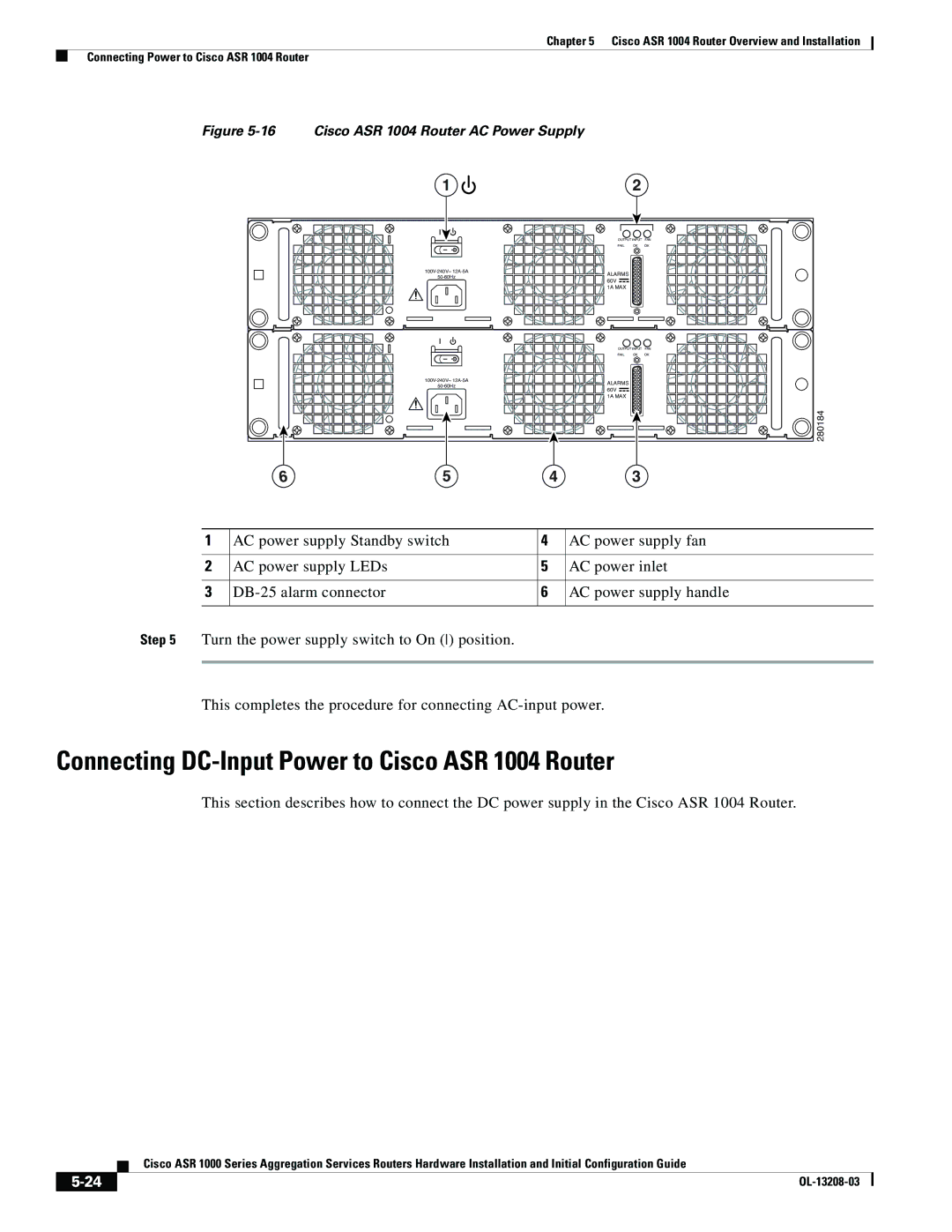
Figure 5-16 Cisco ASR 1004 Router AC Power Supply
1 |
| 2 |
|
| OUTPUT INPUT FAN | ||
| FAIL | OK | OK |
ALARMS |
|
| |
|
| ||
60V |
|
| |
|
|
| |
| 1A MAX |
|
|
| OUTPUT INPUT FAN | ||
| FAIL | OK | OK |
ALARMS |
|
| |
|
| ||
60V |
|
| |
|
|
| |
| 1A MAX |
|
|
|
|
| 280184 |
5 | 4 | 3 |
|
1 | AC power supply Standby switch | 4 | AC power supply fan |
|
|
|
|
2 | AC power supply LEDs | 5 | AC power inlet |
|
|
|
|
3 | 6 | AC power supply handle | |
|
|
|
|
Step 5 Turn the power supply switch to On () position.
This completes the procedure for connecting
Connecting DC-Input Power to Cisco ASR 1004 Router
This section describes how to connect the DC power supply in the Cisco ASR 1004 Router.
Cisco ASR 1000 Series Aggregation Services Routers Hardware Installation and Initial Configuration Guide
|
| |
|
