Chapter 5 Cisco ASR 1004 Router Overview and Installation
Attaching a Chassis Ground Connection
Warning This equipment must be grounded. Never defeat the ground conductor or operate the equipment in the absence of a suitably installed ground conductor. Contact the appropriate electrical inspection authority or an electrician if you are uncertain that suitable grounding is available. Statement 1024
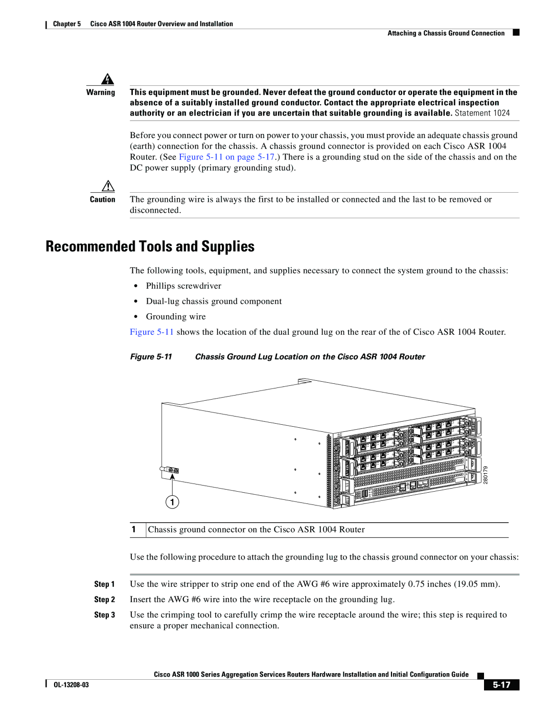
Before you connect power or turn on power to your chassis, you must provide an adequate chassis ground (earth) connection for the chassis. A chassis ground connector is provided on each Cisco ASR 1004 Router. (See Figure
Caution The grounding wire is always the first to be installed or connected and the last to be removed or disconnected.
Recommended Tools and Supplies
The following tools, equipment, and supplies necessary to connect the system ground to the chassis:
•Phillips screwdriver
•
•Grounding wire
Figure 5-11 shows the location of the dual ground lug on the rear of the of Cisco ASR 1004 Router.
Figure 5-11 Chassis Ground Lug Location on the Cisco ASR 1004 Router
1
![]()
![]() 1
1 ![]()
![]() 0
0 ![]()
![]()
![]()
![]()
![]()
![]()
| |
3 | 1 |
2 | 0 |
1 |
|
0 | |
| |
3 |
|
2 |
|
1 | 1 |
0 | 0 |
| |
3 | 1 |
2 | 0 |
1 |
|
0 | |
| |
3 |
|
2 |
|
1 |
|
0 |
|
|
|
|
|
|
|
| LINK | AUX |
|
|
|
|
|
|
| CON | |
|
|
|
| HD | CARRIE | R | BITS | MGMT ETHERNET |
|
|
|
| USB |
|
| ||
|
| CRIT |
|
|
|
|
| |
PWR | ACTV | MAJ |
| DF |
|
|
|
|
|
| DISK |
|
|
|
| ||
STAT | STBY | MIN | 0 | 1 |
|
|
|
|
|
|
|
|
|
|
| ||
![]()
![]() SPA-4XOC3-POS
SPA-4XOC3-POS![]()
![]()
![]()
![]()
![]() 3
3 ![]()
![]() 2
2 ![]()
![]()
![]()
![]()
![]()
![]()
![]()
![]()
![]()
![]()
![]() SPA-4XOC3-POS
SPA-4XOC3-POS![]() 3 2
3 2![]()
![]()
![]()
![]() SPA-4XOC3-POS
SPA-4XOC3-POS![]()
![]() 3
3 ![]()
![]()
![]() 2
2 ![]()
![]()
![]()
![]()
![]()
![]()
![]()
![]() SPA-4XOC3-POS
SPA-4XOC3-POS![]()
![]()
![]() 3
3![]() 2
2![]()
![]()
![]()
280179
1
Chassis ground connector on the Cisco ASR 1004 Router
Use the following procedure to attach the grounding lug to the chassis ground connector on your chassis:
Step 1 Use the wire stripper to strip one end of the AWG #6 wire approximately 0.75 inches (19.05 mm).
Step 2 Insert the AWG #6 wire into the wire receptacle on the grounding lug.
Step 3 Use the crimping tool to carefully crimp the wire receptacle around the wire; this step is required to ensure a proper mechanical connection.
|
| Cisco ASR 1000 Series Aggregation Services Routers Hardware Installation and Initial Configuration Guide |
|
| |
|
|
| |||
|
|
|
|
| |
|
|
|
| ||
