Chapter 2 Cisco ASR 1000 Series Routers Components
Cisco ASR 1000 Series Router Power Supplies
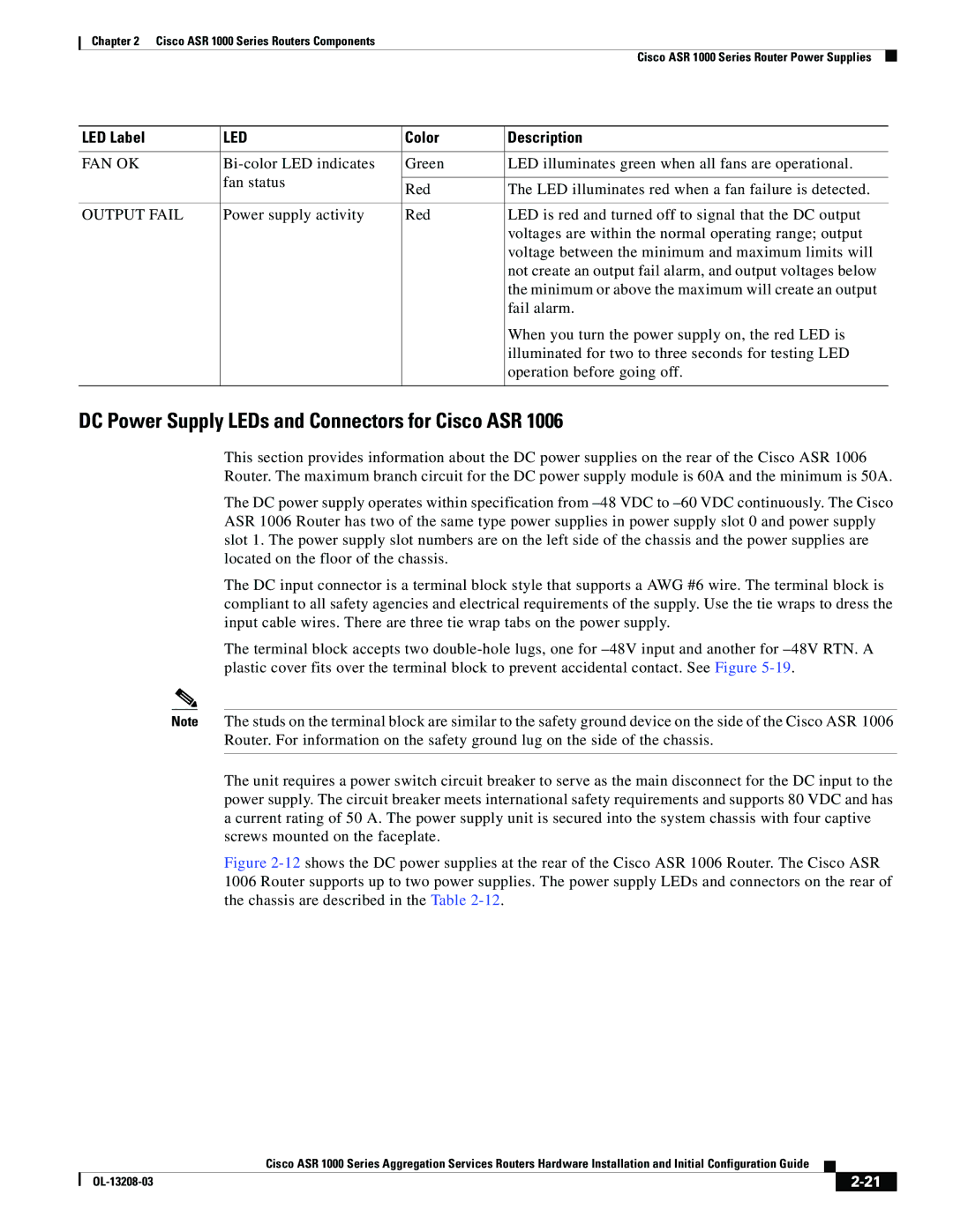
LED Label | LED | Color | Description |
|
|
|
|
FAN OK | Green | LED illuminates green when all fans are operational. | |
| fan status |
|
|
| Red | The LED illuminates red when a fan failure is detected. | |
|
| ||
|
|
|
|
OUTPUT FAIL | Power supply activity | Red | LED is red and turned off to signal that the DC output |
|
|
| voltages are within the normal operating range; output |
|
|
| voltage between the minimum and maximum limits will |
|
|
| not create an output fail alarm, and output voltages below |
|
|
| the minimum or above the maximum will create an output |
|
|
| fail alarm. |
|
|
| When you turn the power supply on, the red LED is |
|
|
| illuminated for two to three seconds for testing LED |
|
|
| operation before going off. |
|
|
|
|
DC Power Supply LEDs and Connectors for Cisco ASR 1006
This section provides information about the DC power supplies on the rear of the Cisco ASR 1006 Router. The maximum branch circuit for the DC power supply module is 60A and the minimum is 50A.
The DC power supply operates within specification from
The DC input connector is a terminal block style that supports a AWG #6 wire. The terminal block is compliant to all safety agencies and electrical requirements of the supply. Use the tie wraps to dress the input cable wires. There are three tie wrap tabs on the power supply.
The terminal block accepts two
Note The studs on the terminal block are similar to the safety ground device on the side of the Cisco ASR 1006 Router. For information on the safety ground lug on the side of the chassis.
The unit requires a power switch circuit breaker to serve as the main disconnect for the DC input to the power supply. The circuit breaker meets international safety requirements and supports 80 VDC and has a current rating of 50 A. The power supply unit is secured into the system chassis with four captive screws mounted on the faceplate.
Figure 2-12 shows the DC power supplies at the rear of the Cisco ASR 1006 Router. The Cisco ASR 1006 Router supports up to two power supplies. The power supply LEDs and connectors on the rear of the chassis are described in the Table 2-12.
|
| Cisco ASR 1000 Series Aggregation Services Routers Hardware Installation and Initial Configuration Guide |
|
| |
|
|
| |||
|
|
|
| ||
|
|
|
| ||