Chapter 5 Cisco ASR 1004 Router Overview and Installation
Connecting Power to Cisco ASR 1004 Router
•Use a crossover cable to connect to an MDI port
•Use a
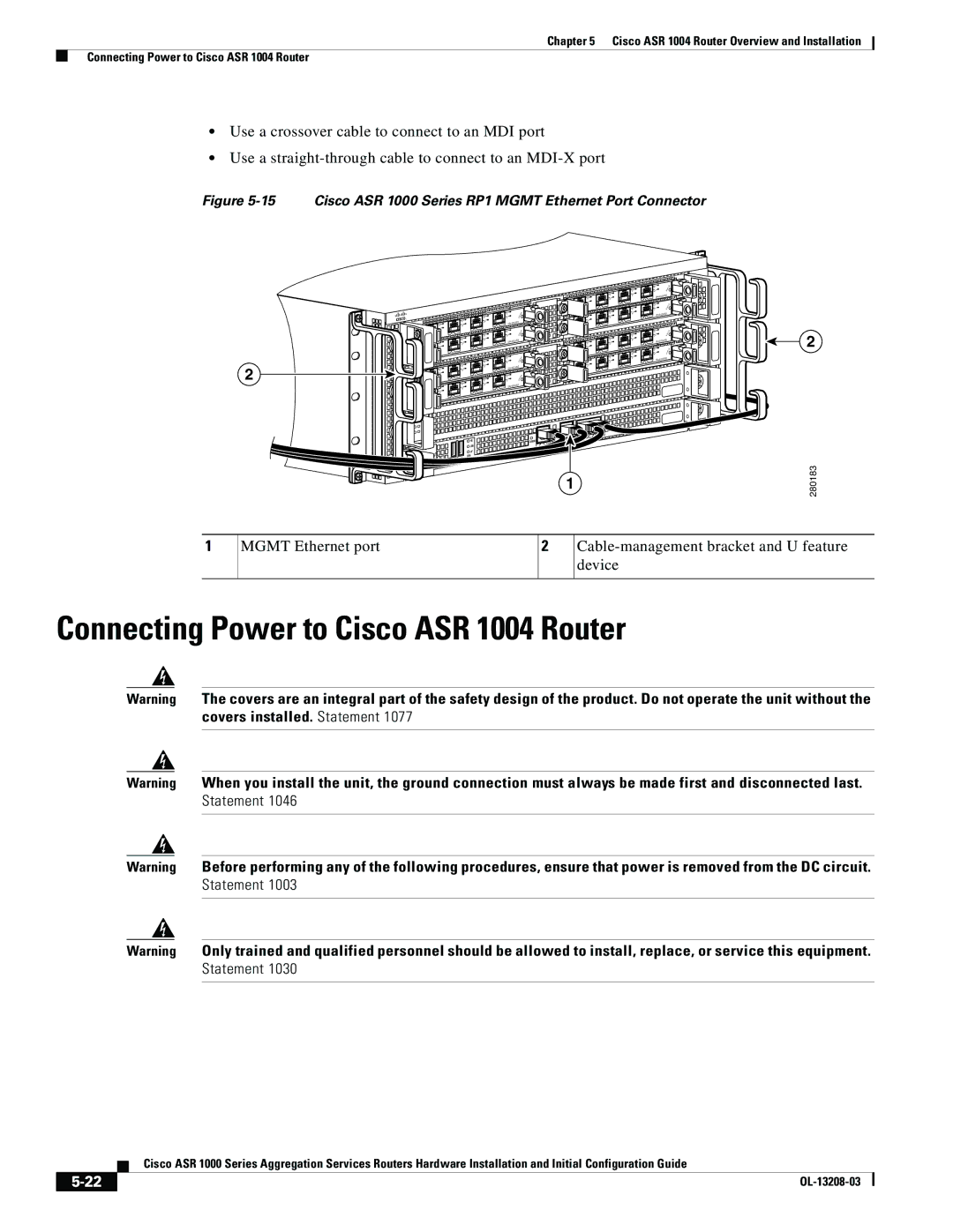
Figure 5-15 Cisco ASR 1000 Series RP1 MGMT Ethernet Port Connector
2
| 2 |
| 1 |
| 0 |
2 | |
3 | 1 |
2 | 0 |
1 |
|
0 |
|
| |
3 |
|
2 | 2 |
1 | 1 |
0 | 0 |
|
|
|
|
|
|
| 2 | |
|
|
|
|
|
| 3 |
| 1 |
|
|
|
|
|
| 2 |
| 0 |
|
|
|
| 1 |
|
|
|
|
|
| 0 |
|
|
|
|
| |
|
|
|
|
|
|
|
| |
|
|
|
|
|
| 3 |
|
|
|
|
|
|
|
| 2 |
|
|
|
|
|
| 1 |
|
|
|
|
|
| 0 |
|
|
|
|
|
|
|
|
|
|
|
| LINK |
| AUX |
|
|
|
|
|
|
| CON | |
|
|
|
|
| HD | CARRIER | MGMT | ETHE |
|
|
|
|
| USB | BITS |
|
|
|
| CRIT |
|
|
|
|
| |
|
|
|
|
|
|
|
| |
| ACTV | MAJ |
| O | DF |
|
|
|
PWR |
| AC |
| DISK |
|
|
| |
STBY | MIN |
| 0 | 1 |
|
|
| |
STAT |
|
|
|
|
| |||
ASR1000 |
|
|
|
|
|
|
| |
|
|
|
|
|
|
|
|
1
![]() SPA-4XOC3-POS
SPA-4XOC3-POS ![]() 3
3![]()
![]()
![]()
![]()
![]() SPA-4XOC3-POS
SPA-4XOC3-POS ![]()
![]()
![]() 3
3![]()
![]() SPA-4XOC3-POS
SPA-4XOC3-POS ![]()
![]() 3
3 ![]()
![]()
![]()
![]()
![]()
![]() SPA-4XOC3-POS
SPA-4XOC3-POS ![]()
![]()
![]()
![]() 3
3![]()
![]()
![]()
![]()
2
280183
1
MGMT Ethernet port
2
Connecting Power to Cisco ASR 1004 Router
Warning The covers are an integral part of the safety design of the product. Do not operate the unit without the covers installed. Statement 1077
Warning When you install the unit, the ground connection must always be made first and disconnected last. Statement 1046
Warning Before performing any of the following procedures, ensure that power is removed from the DC circuit. Statement 1003
Warning Only trained and qualified personnel should be allowed to install, replace, or service this equipment. Statement 1030
| Cisco ASR 1000 Series Aggregation Services Routers Hardware Installation and Initial Configuration Guide |
|
