Programmer’s Reference Manual PRM
Intel 815 Chipset Graphics Controller
Intel 815 Chipset Graphics Controller PRM, Rev
Contents
100
106
141
Monosrccopyimmediateblt
Gfxrenderstatemaplodlimits
15.4.3.3 HORZPH-Horizontal Phase Register 279 15.4.3.4
16.2.5
Figures
Tables
Date
Revision History
Rev
This page is intentionally left blank
Term Description
Introduction
Terminology
MCH
Reference Documents
Intel 815 Chipset Overview
Intel 82815 Chipset Gmch Overview
I/O Controller Hub
Host Interface
Intel 82815 Chipset Gmch Block Diagram
Multiplexed AGP and Display Cache Interface
Data Rate Signaling Level
System Memory Interface
Intel 82815 Chipset Gmch Integrated Graphics Support
Hub Interface
Front Side Bus System Memory Display Cache Interface
Gmch Power Delivery
Three PCI Devices on Gmch
System Clocking
Multi-Mode Capability Requirements
Supported Single Monitor and Multi-monitor Configurations
Configuration Single Monitor Multi-monitor
System Startup
Device Mode Auto-Detect Flowchart
Software Start-Up Sequence
Graphics Driver Startup
Switching Device modes
System Memory Space
System Address Map
Graphics Controller Register Memory and I/O Map
Memory and I/O Space Registers
Reserved 50000h−5FFFFh. Reserved in the Intel 815 chipset
Instruction and Interrupt Control Registers 01000h −02FFFh
Address Offset Symbol Register Name Access
GC Register Memory Address Map
VGA and VGA Extended Registers
Instpm
OV0ADD
Ssladd
Display and Cursor Control Registers 70000h-7FFFFh
VGA and Extended VGA Register Map
Address Register Name Read Register Name Write 2D Registers
VGA and Extended VGA I/O and Memory Register Map
Index Sym Register Name
Indirect VGA and Extended VGA Register Indices
Index Sym Description
2D Attribute Controller Registers 3C0h / 3C1h
CR0F
Graphics Address Translation
GTT
Memory Buffers for GC’s Instruction Interface
Graphics Translation Table GTT Range Definition
This page is intentionally left blank
Hardware Detection Probe
Basic Initialization Procedures
Vendor Id Device Id PCI Device Characteristics
Initialization Sequence
Frame Buffer Initialization
Protect Registers Locking and Unlocking
Hardware Register Initialization
Hardware State
Color vs. Monochrome Monitors
Saving the Hardware State
Restoring the Hardware State
Intel 815 Chipset Graphics Controller PRM, Rev
Intel 815 Chipset Graphics Controller PRM, Rev
This page is intentionally left blank
BLT Engine Programming Considerations
When the Source and Destination Locations Overlap
Blt Engine Programming
Source
Bblt3.vsd
Destination Source Bblt4.vsd
Contiguous vs. Discontinuous Graphics Data
Basic Graphics Data Considerations
Source Data
Monochrome Source Data
Pattern Data -- Always an 8x8 Array of Pixels
Pattern Data
Bpp Pattern Data -- Occupies 64 Bytes 8 quadwords
Destination Data
Pattern Fill -- a Very Simple BLT
BLT Programming Examples
Pattern Data for Example Pattern Fill BLT
Results of Example Pattern Fill BLT
On-Screen Destination for Example Character Drawing BLT
Drawing Characters Using a Font Stored in System Memory
Intel 815 Chipset Graphics Controller PRM, Rev
Results of Example Character Drawing BLT
SMRAM-System Management RAM Control Register Device
Initialization Registers
Standard VGA Registers
Smram Registers
RAM
Bit Description
Initialization and Usage of Stolen Memory
Display and Cursor Control Registers
Clock Control and Power Management Registers
LCD/TV-Out
CRT Controller Registers 3B4h/3D4h/3B5h/3D5h
Graphics Controller Registers 3CEh / 3CFh
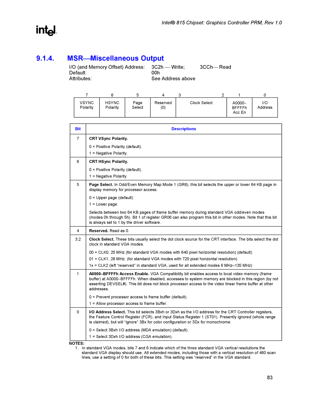
MSR
Initialization Values for VGA Registers
GR01 00h
This page is intentionally left blank
Frame Buffer Access
Intel 815 Chipset Graphics Controller PRM, Rev
Offset
VGA and Extended VGA Registers
General Control & Status Registers
Name Function Read Write Memory
Bit
1. ST00Input Status
Vertical Retrace/Video
Display Enable Output
ST01Input Status
Bit Descriptions
Reserved. Read as Vsync Control
FCRFeature Control
CRT HSync Polarity
MSRMiscellaneous Output
CRT VSync Polarity
SRXSequencer Index
Sequencer Registers
2. SR00Sequencer Reset
Shift
3. SR01Clocking Mode
4. SR02Plane/Map Mask
Bit 10,4 Map Number Table Location
5. SR03Character Font
Bit 32 Map Number Table Location
Made according to the value of the Plane Mask Register SR02
6. SR04Memory Mode Register
Bit Description Horizontal Character Counter
7. SR07Horizontal Character Counter Reset
Graphics Controller Registers
GRXGRX Graphics Controller Index Register
3. GR01Enable Set/Reset Register
2. GR00Set/Reset Register
5. GR03Data Rotate Register
4. GR02Color Compare Register
6. GR04Read Plane Select Register
7. GR05Graphics Mode Register
Bits 65=1x
Bits 65=00
Bits 65=01
Write Mode
Odd/Even Mode
Read Mode
Bit
Graphics/Text Mode
8. GR06Miscellaneous Register
Bit Mask
9. GR07Color Don’t Care Register
10. GR08Bit Mask Register
VGA Buffer/Memory Map Select
Reserved To Local Memory Enable
Packed Mode Enable
11. GR10Address Mapping
Supported
12. GR11Page Selector
13. GR141FSoftware Flags
Memory Offset Address 3CFh Index=14h-1fh Default Attribute
ARXAttribute Controller Index Register
Attribute Controller Registers
Pixel Width/Clock Select
2. AR000FPalette Registers 0F
3. AR10Mode Control Register
Palette Bits P5, P4 Select
Pixel Panning Compatibility
Enable Blinking/Select Background Intensity
Enable Line Graphics Character Code
Graphics/Alphanumeric Mode
Bit 54 ST01 Bit
5. AR12Memory Plane Enable Register
4. AR11Overscan Color Register
Pixel Text Graphics
6. AR13Horizontal Pixel Panning Register
Reserved
Pixel Text Color
7. AR14Color Select Register
VGA Color Palette Registers
DACMASKPixel Data Mask Register
Bits Index Register Indicated
DACSTATEDAC State Register
DACRXPalette Read Index Register
DACWXPalette Write Index Register
DACDATAPalette Data Register
CRT Controller Register
CRXCRT Controller Index Register
Display Fields and Dimensions CRxx Control Registers
4. CR02Horizontal Blanking Start Register
3. CR01Horizontal Display Enable End Register
2. CR00Horizontal Total Register
6. CR04Horizontal Sync Start Register
Bit Amount of Delay
5. CR03Horizontal Blanking End Register
7. CR05Horizontal Sync End Register
9. CR07Overflow Register
8. CR06Vertical Total Register
115
116
10. CR08Preset Row Scan Register
11. CR09Maximum Scan Line Register
Double Scanning Enable
13. CR0BText Cursor End Register
12. CR0AText Cursor Start Register
14. CR0CStart Address High Register
16. CR0EText Cursor Location High Register
15. CR0DStart Address Low Register
18. CR10Vertical Sync Start Register
17. CR0FText Cursor Location Low Register
19. CR11Vertical Sync End Register
CR13Offset Register
20. CR12Vertical Display Enable End Register
CR145 CR173 Address Incrementing Interval
CR146 CR176 Addressing Mode
22. CR14Underline Location Register
Count By
24. CR16Vertical Blanking End Register
23. CR15Vertical Blanking Start Register
CR146 CR176
25. CR17CRT Mode Control
Word Mode or Byte Mode
Select Row Scan Counter
Compatibility Mode Support
Memory Address Counter Address Bits
DWord Mode
CR17 bit 1=1 CR17 bit 1=0 CR17 bit 0=1 CR17 bit 0=0
Frame Buffer Address Decoder
27. CR22Memory Read Latch Data Register
26. CR18Line Compare Register
29. CR30Extended Vertical Total Register
30. CR31Extended Vertical Display End Register
31. CR32Extended Vertical Sync Start Register
32. CR33Extended Vertical Blanking Start Register
Extended Horizontal Total MSB that extends CR00
33. CR35 Extended Horizontal Total Time Register
34. CR39Extended Horizontal Blank Time Register
35. CR40Extended Start Address Register
37. CR42Extended Start Address High Register
36. CR41Extended Offset Register
39. CR80I/O Control
Interlace Enable
38. CR70Interlace Control Register
41. CR82Blink Rate Control
40. CR81Reserved
Overview
Programming Interface
Reserved Bits and Software Compatibility
Instruction Transport Overview
GC Register Programming
GC Instruction Streams
Instruction Use
Interrupt Ring
Instruction Parser
Ring Buffer Registers
Ring Buffers RB
Ring Buffer Use
Characteristic Description
Ring Buffer Initialization
Batch Buffer Sequence
Batch Buffers
Wait Instructions
Instruction Arbitration
Arbitration Rationale
Instruction Arbitration Rules
Batch Buffer Protected Mode
Instruction Arbitration Points
Instructions
Instruction Format
Instruction Parser Instructions
3129 2824 210
Bits
Client Instruction
Graphics Controller Instructions
Client
DWord Bit Description
Instruction Parser Instructions
Introduction
Instruction Descriptions
Reserved MBZ
Opcode 01h
Opcode 02h
DWord Bit
Gfxcmdparserwaitforevent
DWord Bits Description
Dwordlength 00h
Opcode 15h
Reserved 00000h
Dword Length 00h
Instruction Target 14h
Flip type 0 Synch flip, 1 Async flip
Opcode 07h
Opcode 16h
Instruction Target 12h
Opcode 08h
Arbitration ON/OFF
Instruction Target 11h
Word Bits Description
Instruction Target 30h
Gfxcmdparserbatchbuffer
BLT Engine Instructions
Instructions
BLTs To and From Cacheable Memory
Setupblt
Dword Length 06h
Setup Background Color All
Setup Foreground Color SLB & TB only
Instruction Target Opcode 00h
Raster Operation
Instruction Target Opcode 10h
Dword Length 07h
Color Depth
Destination X2 Coordinate Ending Right
Pixelblt
Instruction Target Opcode 20h
Instruction Target Opcode 21h
Dword Length 04h
Textblt
Instruction Target Opcode 22h
Immediate Data DWs 2 through Dwordlength DWL
TEXTImmediateBLT
Instruction Target Opcode 30h
Immediate Data DW
Solid Pattern Color
Colorblt
Instruction Target Opcode 40h
Dword Length 03h
Instruction Target Opcode 41h
Patblt
Pattern Background Color
Mono Pattern Transparency Mode 1 = transparency enabled
Monopatblt
Instruction Target Opcode 42h
Instruction Target Opcode 43h
Srccopyblt
Line
Instruction Target Opcode 44h
Source Foreground Color
Source Background Color
Instruction Target Opcode 61h
Mono Source Transparency Mode 1 = transparency enabled
Instruction Target Opcode 45h
Destination Transparency Mode See BR00 definition
Fullblt
Destination Transparency Color
Fullmonosrcblt
Instruction Target Opcode 46h
Dword Length 09h
Instruction Target Opcode 47h
181
Dword Length 0Ah
Instruction Target Opcode 48h
183
12.3.1. BR00-BLT Opcode and Control
BLT Engine Instruction Definitions
185
SolPat Rsvd Mono
187
12.3.4. BR03-Clip Rectangle Y2 Address
12.3.3. BR02-Clip Rectangle Y1 Address
3128 Reserved. Must be Zero 2716
12.3.5. BR04-Clip Rectangle X1
12.3.7. BR06-Setup Expansion Foreground Color
12.3.6. BR05-Setup Expansion Background Color
12.3.8. BR07-Setup Color Pattern Address
12.3.9. BR08-Destination X1
12.3.11. BR10-Destination Y2 Address
12.3.10. BR09-Destination Address and Destination Y1 Address
Source Pitch Offset or Monochrome Source Quadwords
12.3.13. BR12-Source Address
Increment/Decrement Select
12.3.14. BR13-BLT Raster OP, Control, and Destination Pitch
Dynamic Color Depth
Source Select Mode
12.3.15. BR14-Destination Width & Height
12.3.16. BR15-Color Pattern Address
3124 Reserved. Must be Zero 230
12.3.18. BR17-Pattern Expansion Foreground Color
12.3.20. BR19-Source Expansion Foreground Color
DSLH-Destination Scan Line Height
SSLADD-Source Scan Line Address
DSLRADD-Destination Scan Line Read Address
204
Primitive Winding Order
Rendering Engine Instructions
Gfxprimitive
Axis Aligned Rectangles
Primitive Rendering Instruction Format
Position Mask
Bias
Vertex Attribute Comments
Variable Length Vertex Formats for Rendering Instructions
Gfxvertex
Gfxrenderstatevertexformat
Block Pattern Format
Gfxblock
Rendering Block 1Eh
Block Type
Prediction Type
DWord Bits
Vertical Motion Vector Precision 00 = 1/2 pixel
212
Precision Format Range
Non-pipelined State Variables
Motion Vector Format
Gfxrenderstatemaptexels
Gfxrenderstatemapcoordsets
Normalized Coordinate Set
Update Coordinate Set Index The valid range is
Normalized Coordinate Set Mask 0 = Do not update 1 = Update
Opcode 1h
Gfxrenderstatemapinfo
Walk
Discrete Integrated Base Utilize Fence Tiled Surface
Surface Format
3DstateMW 1Dh
Dwordlength 2h
Reserved 0h
1511
Color Space Conversion Enable
221
Gfxrenderstatemapfilter
Opcode 2h
Reserved 00h Mip Mode Filter Valid values are
Opcode 3h
Gfxrenderstatemaplodlimits
Opcode 4h
Texture LOD Dither Weight Mask 0 = Do not update 1 = Update
Gfxrenderstatemaplodcontrol
Opcode 82h
Gfxrenderstatemappaletteload
3DStateMWNPNon-pipelined 1Dh
Blend Equation Description
Gfxrenderstatemapcolorblendstages
Replicate Arg1 Alpha to Color Channels
Update Blending Stage Index The valid range is
3DState24 00h
Write result to Current Register or Accumulator Select
Invert Color Arg2
Gfxrenderstatemapalphablendstages
Invert Alpha Arg2
3DState24 01h
Invert Alpha Arg1
Instruction 1h
Gfxrenderstatecolorfactor
Gfxrenderstatecolorchromakey
Kill Pixel Mode
KeyedPixelControl
KeyedPixelControl Write Mask 0 = Do not update 1 = Update
Instruction 2h
Monochrome Specular Full Color RGB
Gfxrenderstatesrcdstblendmono
No Specular
236
Opcode Source / Destination Blend State
3DState24NP Non-pipelined 14h
Alpha Reference State Mask 1 = Update 0 = Do Not Update
Gfxrenderstatezbiasalphafuncref
Gfxrenderstatelinewidthcullshade Mode
2824 3DState24 02h
Alpha Shade Mode State Mask 1 = Update 0 = Do Not Update
Specular Shade Mode State Mask 1 = Update 0 = Do Not Update
Color Shade Mode State Mask 1 = Update 0 = Do Not Update
GFXRENDERSTATEBOOLEANENA1
Alpha Setup Enable Enable Mask 1 = Update 0 = Do Not Update
Color Index Key Enable Mask 1 = Update 0 = Do Not Update
Specular Enable State Mask 1 = Update 0 = Do Not Update
GFXRENDERSTATEBOOLEANENA2
Specular Dither Enable Mask 1 = Update 0 = Do Not Update
Frame Buffer Write Enable Mask 1 = Update 0 = Do Not Update
Buffer Write Enable Mask 1 = Update 0 = Do Not Update
3DState24NP Non-pipelined 15h
Gfxrenderstatefogcolor
Gfxrenderstatedrawingrectangleinfo
Opcode 80h
3DStateMWNP Non-pipelined 1Dh
Opcode 10h
Gfxrenderstatescissorenable
Scissor Rectangle Enable Mask 1 = Update 0 = Do Not Update
3DState16NP Non-pipelined 1Ch
Opcode 81h
Gfxrenderstatescissorrectangleinfo
Stipple Pattern
Stipple Pattern
Opcode 83h
Gfxrenderstateantialiasing
Vertex Sequence
Gfxrenderstateprovokingvtxpixelization Rule
Pixelization Rule Mask
Small Triangle Filter Enable Mask
Opcode 85h
Gfxrenderstatedestbuffervariables
Dest Buffer Format 0h = Any 8-bit Surface
Drawing and Scissor Rectangles
Programming Hints/Rules
Color Calculator
255
256
Programming Notes
Clock Control Registers
Example Programming Sequence DCLK2
DCLK0D-Display Clock 0 Divisor Register
DCLK1D-Display Clock 1 Divisor Register
DCLK2D-Display Clock 2 Divisor Register
LCDCLKD-LCD Clock Divisor Register
Reserved VCO Loop Divide LCD Clock
DCLK0DS-Display & LCD Clock Divisor Select Register
Post Divisor Select LCD Clock
VCO Loop Divide clock
Post Divisor Select clock
Internal DAC Enable
PWRCLKC-Power Management and Miscellaneous Clock Control
Overlay Registers
Comment
Register/Instruction Category
Updating Register Values
15.1. OV0ADD-Overlay 0 Register Update Address Register
DOV0STA-Display/Overlay 0 Status Register
GAMC50-Gamma Correction Registers
Gamma Correction
Green Blue
Red
Three times
Mathematical Gamma Correction For Overlay
Latch Address
Gamma Correction Theory Of Operation
Gamma Hardware Implementation
Format Alignment
Memory Offset Registers
Overlay Buffer Pointer Registers
OBUF0Y-Overlay Buffer 0 Y Pointer Register
OBUF0U-Overlay Buffer 0 U Pointer Register
OBUF1Y-Overlay Buffer 1 Y Pointer Register
Bit Descriptiont
OBUF0V-Overlay Buffer 0 V Pointer Register
OBUF1U-Overlay Buffer 1 U Pointer Register
15.4.2.1. OV0STRIDE-Overlay 0 Stride Register
Overlay Stride Registers
OBUF1V-Overlay Buffer 1 V Pointer Register
YRGBVPH-Y/RGB Vertical Phase Register
Overlay Initial Phase Registers
HORZPH-Horizontal Phase Register
UVVPH-UV Vertical Phase Register
INITPH-Initial Phase Register
DWINSZ-Destination Window Size Register
Overlay Destination Window Position/Size Registers
DWINPOS-Destination Window Position Register
SWID-Source Width Register
Overlay Source Size Registers
SWIDQW-Source Width In QWords Register
SHEIGHT-Source Height Register
YRGBSCALE-Y/RGB Scale Factor Register
Overlay Scale Factor Registers
UVSCALE-UV Scale Factor Register
15.4.7.2. OV0CLRC1-Overlay 0 Color Correction 1 Register
Overlay Color Correction Registers
15.4.7.1. OV0CLRC0-Overlay 0 Color Correction 0 Register
DCLRKV-Destination Color Key Value Register
Overlay Destination Color Key Registers
DCLRKM-Destination Color Key Mask Register
Destination Constant Alpha Blend Enable
Always Constant Alpha Blend Enable
SCLRKVH-Source Color Key Value High Register
Overlay Source Color Key Registers
SCLRKM-Source Color Key Mask Register
SCLRKVL-Source Color Key Value Low Register
Source Constant Alpha Blend Enable
15.4.10.1. OV0CONF-Overlay Configuration Register
Overlay Configuration Registers
15.4.11. OV0CMD-Overlay Command Register
Vertical Luminance Filter. Vertical Luminance Filter
Vertical Chrominance Filter. Vertical Chrominance Filter
Automatic flipping
Manual flip command
Source Format
297
AWINPOS-Alpha Blend Window Position Register
Overlay Alpha Blend Window Position/Size Registers
AWINSZ-Alpha Blend Window Size Register
Overlay Flip Instruction
300
FENCE-Graphics Memory Fence Table Registers
Instruction, Memory, and Interrupt Control Registers
Instruction Control Registers
Fence Pitch
Reserved for address bits 31 downto
Tile walk
Fence size
Normal Invalidation Mechanism
PGTBLCTL-Page Table Control Register
PGTBLER-Page Table Error Register
Error Type
PGTBLERRMSK-Page Table Error Mask Register
Display Page Table Error Mask
Buffer Unit Page Table Error Mask
Command Streamer DMA Page Table Error Mask
Overlay Page Table Error Mask
Intel 810 Chipset and Intel815 Chipset Errata
RINGBUF-Ring Buffer Registers
Ring Buffer Valid
Reserved
DWord Description Offset
HWSPGA-Hardware Status Page Address Register
IPEHR-Instruction Parser Error Header Register debug
IPEIR-Instruction Parser Error Identification Register debug
INSTDONE-Instruction Stream Interface Done Register
This read only register reports engine done signals
NOPID-NOP Identification Register
Disable State Variable Updates
INSTPM-Instruction Parser Mode Register
INSTPS-Instruction Parser State Register debug
Cscpr State Machine Command Parser
ABBSTR-Active Batch Buffer Start Address Register debug
BBPPTR-Batch Buffer Parser Pointer Register debug
Current DMA Address Reserved User of the DMA Engine
ABBEND-Active Batch Buffer End Address Register debug
DMAFADD-DMA Engine Fetch Address debug
Instruction Fifo Debug Mode
MEMMODE-Memory Interface Mode Register debug
Reserved Host Graphics Prefetch Mode
Graphics Address Translation Mode
Bit Definition For Interrupt Control Registers
Interrupt Control Registers
321
HWSTAM-Hardware Status Mask Register
Interrupt Enables. See Table
IER-Interrupt Enable Register
Interrupt Identity. See. Table
IIR-Interrupt Identity Register
Interrupt Mask Bits. See. Table
IMR-Interrupt Mask Register
ISR-Interrupt Status Register
Table Error handling in Intel 815 Chipset
Error Identity, Mask and Status Registers
Table Error
Resetting the Page Table Error
EMR-Error Mask Register
EIR-Error Identity Register
ESR-Error Status Register
FWBLC-FIFO Watermark and Burst Length Control
Display Interface Control
332
HTOTAL-Horizontal Total Register
LCD / TV-Out Register Description
HBLANK-Horizontal Blank Register
HSYNC-Horizontal Sync Register
VTOTAL-Vertical Total Register
VBLANK-Vertical Blank Register
VSYNC-Vertical Sync Register
Sync Polarity Control
LCD / TV-Out Enable
LCDTVC-LCD/TV-Out Control Register
Fphsync Control
FP Vesa VGA Mode
FP / 740 Data Ordering
Fpvsync Control
Active Data Polarity
Border Enable
Fphsync Output Control
Active Data Order
BCLRPAT- Border Color Pattern Register
OVRACT-Overlay Active Register
DRT-DRAM Row Type
Local Memory Interface
Bit RAS# act. To precharge t RAS Refresh to RAS# act. t RC
Reserved Paging Mode Control PMC
Bit RAS#-to-CAS# delay t RCD
DRAMCL-DRAM Control Low
DRAMCH-DRAM Control High
346
HSYNC/VSYNC Control1916
19. I/O Control Registers
HVSYNC-HSYNC/VSYNC Control Register
GPIOAGeneral Purpose I/O Control Register a
Gpio Registers
Value .bit
GPIOBGeneral Purpose I/O Control Register B
351
352
Line Counter for Display
Display And Cursor Registers
DISPSL-Display Scan Line Count
Inclusive / Exclusive
DISPSLC-Display Scan Line Count Range Compare
Pixel Pipeline Control
PIXCONF-Pixel Pipeline Configuration
Reserved Display path Graphics Gamma Enable. See note
Overlay path Gamma Enable. See note
CRT Overscan Color
Display Color Mode
Bit DAC Enable
Enable Extended Status Read Mode
SWF13-Software Flag Registers
GUI Mode
Transition from VGA modes to hires mode or opposite
BLTCNTL-BLT Control
DPLYBASE-Display Base Address Register
DPLYSTAS-Display Status Select Register
Reserved Flat Panel Hot Plug Detect Enable
Vertical Sync Status Enable
Display Line Compare Enable
Vertical Sync Status
Vertical Blank Enable
Overlay Registers Upated Enable
Overlay Registers Updated Status
Reserved Cursor Coordinate System Origin Select
Hardware Cursor
CURCNTR-Cursor Control Register
CURPOS-Cursor Position Register
CURBASE-Cursor Base Address Register
Appendix a Mode Parameters
Parameters for Screen Resolution/Refresh Rate 320x20070Hz =
Parameters for Screen Resolution/Refresh Rate 320x24070Hz =
Parameters for Screen Resolution/Refresh Rate 352X48070Hz =
Parameters for Screen Resolution/Refresh Rate 352X57670Hz =
Parameters for Screen Resolution/Refresh Rate 400x30070Hz =
Parameters for Screen Resolution/Refresh Rate 512X38470Hz =
Parameters for Screen Resolution/Refresh Rate 640x35085Hz =
Parameters for Screen Resolution/Refresh Rate 640x40070Hz =
Parameters for Screen Resolution/Refresh Rate 640x40085Hz =
Parameters for Screen Resolution/Refresh Rate 640x48060Hz =
Parameters for Screen Resolution/Refresh Rate 640x48070Hz =
Parameters for Screen Resolution/Refresh Rate 640x48072Hz =
Parameters for Screen Resolution/Refresh Rate 640x48075Hz =
Parameters for Screen Resolution/Refresh Rate 640x48085Hz =
Parameters for Screen Resolution/Refresh Rate 720x40085Hz =
Parameters for Screen Resolution/Refresh Rate 720x48060Hz =
Parameters for Screen Resolution/Refresh Rate 720x48075Hz =
Parameters for Screen Resolution/Refresh Rate 720x48085Hz =
Parameters for Screen Resolution/Refresh Rate 720x57660Hz =
Parameters for Screen Resolution/Refresh Rate 720x57675Hz =
Parameters for Screen Resolution/Refresh Rate 720x57685Hz =
Parameters for Screen Resolution/Refresh Rate 800x60056Hz =
Parameters for Screen Resolution/Refresh Rate 800x60060Hz =
Parameters for Screen Resolution/Refresh Rate 800x60070Hz =
Parameters for Screen Resolution/Refresh Rate 800x60072Hz =
Parameters for Screen Resolution/Refresh Rate 800x60075Hz =
Parameters for Screen Resolution/Refresh Rate 800x60085Hz =
Parameters for Screen Resolution/Refresh Rate 854X48060Hz =
Parameters for Screen Resolution/Refresh Rate 854X48075Hz =
Parameters for Screen Resolution/Refresh Rate 854X48085Hz =
394
395
396
397
398
399
400
401
402
403
404
405
406
407
408
409
410
411
412
413
414
415
416
417
418
419
420
421
422
Intel around the world