Menu 9—Input Setup, continued
Menu 9 Displays with Key Entries
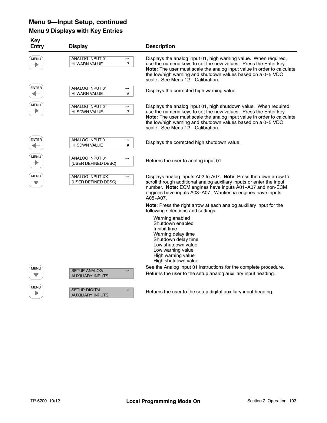
Key |
|
|
Entry | Display | Description |
ANALOG INPUT 01 | → |
HI WARN VALUE | ? |
Displays the analog input 01, high warning value. When required, use the numeric keys to set the new values. Press the Enter key. Note: The user must scale the analog input value in order to calculate the low/high warning and shutdown values based on a
ANALOG INPUT 01 | → |
HI WARN VALUE | # |
|
|
ANALOG INPUT 01 | → |
HI SDWN VALUE | ? |
Displays the corrected high warning value.
Displays the analog input 01, high shutdown value. When required, use the numeric keys to set the new values. Press the Enter key. Note: The user must scale the analog input value in order to calculate the low/high warning and shutdown values based on a
ANALOG INPUT 01 | → |
HI SDWN VALUE | # |
|
|
ANALOG INPUT 01 | → |
(USER DEFINED DESC) |
|
|
|
|
|
ANALOG INPUT XX | → |
(USER DEFINED DESC) |
|
SETUP ANALOG | → |
AUXILIARY INPUTS |
|
|
|
SETUP DIGITAL | → |
AUXILIARY INPUTS |
|
|
|
Displays the corrected high shutdown value.
Returns the user to analog input 01.
Displays analog inputs A02 to A07. Note: Press the down arrow to scroll through additional analog auxiliary inputs or enter the input number. Note: ECM engines have inputs
Note: Press the right arrow at each analog auxiliary input for the following selections and settings:
Warning enabled Shutdown enabled Inhibit time Warning delay time Shutdown delay time Low shutdown value Low warning value High warning value High shutdown value
See the Analog Input 01 instructions for the complete procedure. Returns the user to the setup analog auxiliary input heading.
Returns the user to the setup digital auxiliary input heading.
| Local Programming Mode On | Section 2 Operation 103 |