6.1.5Ground Fault Annunciation
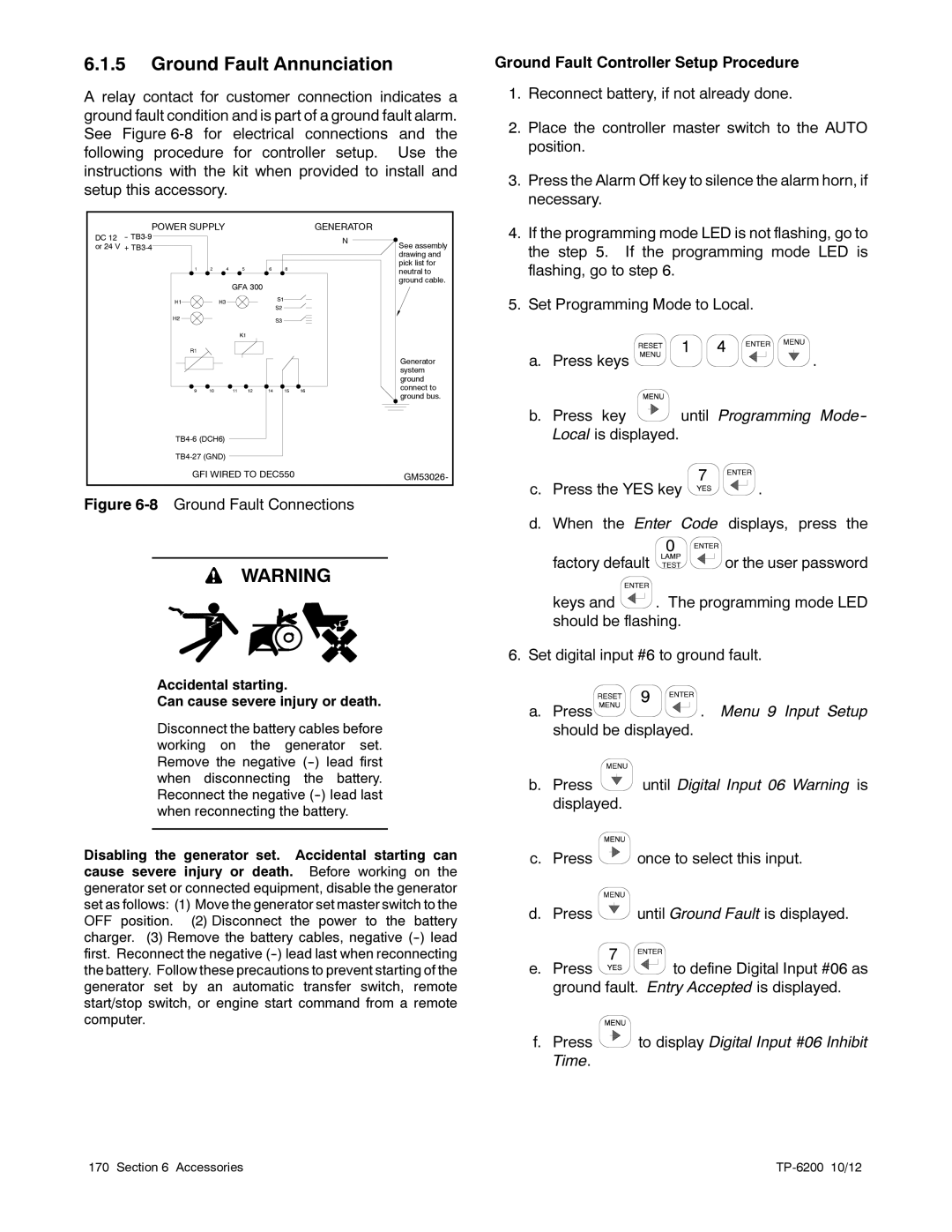
A relay contact for customer connection indicates a ground fault condition and is part of a ground fault alarm. See Figure
POWER SUPPLY | GENERATOR |
| |
DC 12 | N |
| |
or 24 V + | See assembly | ||
| |||
|
| drawing and | |
|
| pick list for | |
|
| neutral to | |
| GFA 300 | ground cable. | |
|
|
| Generator |
| system |
| ground |
| connect to |
| ground bus. |
| |
| |
GFI WIRED TO DEC550 | GM53026- |
|
Figure 6-8 Ground Fault Connections
WARNING
Accidental starting.
Can cause severe injury or death.
Disconnect the battery cables before working on the generator set. Remove the negative
Disabling the generator set. Accidental starting can cause severe injury or death. Before working on the generator set or connected equipment, disable the generator set as follows: (1) Move the generator set master switch to the OFF position. (2) Disconnect the power to the battery charger. (3) Remove the battery cables, negative
Ground Fault Controller Setup Procedure
1.Reconnect battery, if not already done.
2.Place the controller master switch to the AUTO position.
3.Press the Alarm Off key to silence the alarm horn, if necessary.
4.If the programming mode LED is not flashing, go to the step 5. If the programming mode LED is flashing, go to step 6.
5.Set Programming Mode to Local.
a.Press keys ![]()
![]()
![]()
![]() .
.
b.Press key ![]() until Programming
until Programming
c.Press the YES key ![]()
![]() .
.
d.When the Enter Code displays, press the
factory default ![]()
![]() or the user password
or the user password
keys and ![]() . The programming mode LED should be flashing.
. The programming mode LED should be flashing.
6.Set digital input #6 to ground fault.
a.Press![]()
![]() . Menu 9 Input Setup should be displayed.
. Menu 9 Input Setup should be displayed.
b.Press ![]() until Digital Input 06 Warning is displayed.
until Digital Input 06 Warning is displayed.
c.Press ![]() once to select this input.
once to select this input.
d.Press ![]() until Ground Fault is displayed.
until Ground Fault is displayed.
e.Press ![]()
![]() to define Digital Input #06 as ground fault. Entry Accepted is displayed.
to define Digital Input #06 as ground fault. Entry Accepted is displayed.
f.Press ![]() to display Digital Input #06 Inhibit Time.
to display Digital Input #06 Inhibit Time.
170 Section 6 Accessories |
|