2.7 Reviewing Menu Displays
Use this section to review a summary of the generator set controller data. See Figure
Press the Reset key, enter the desired menu number key(s), and then press the Enter key. Use the down arrow and right arrow keys for navigation.
See Section 1, Specifications and Features, to review set point ranges and default settings for comparison to the actual setup.
The user must enable the programming mode to edit the display. See Menu
Note: Press any key on the keypad to activate the controller panel display. The panel display turns off 5 minutes after the last keypad entry.
Note: Press the Reset Menu key to clear error messages.
Note: Press the Menu Right → key prior to entering decimal values where necessary.
Menus displaying the # symbol represent one of the following data types:
D
D
D
Menus displaying the ? symbol require the user to enter data.
Menus displaying the * symbol represent access code or password type entries. The actual key entry does not display.
See Section 2.5.3, Request and Error Messages, for error display messages and explanations while navigating the menus.
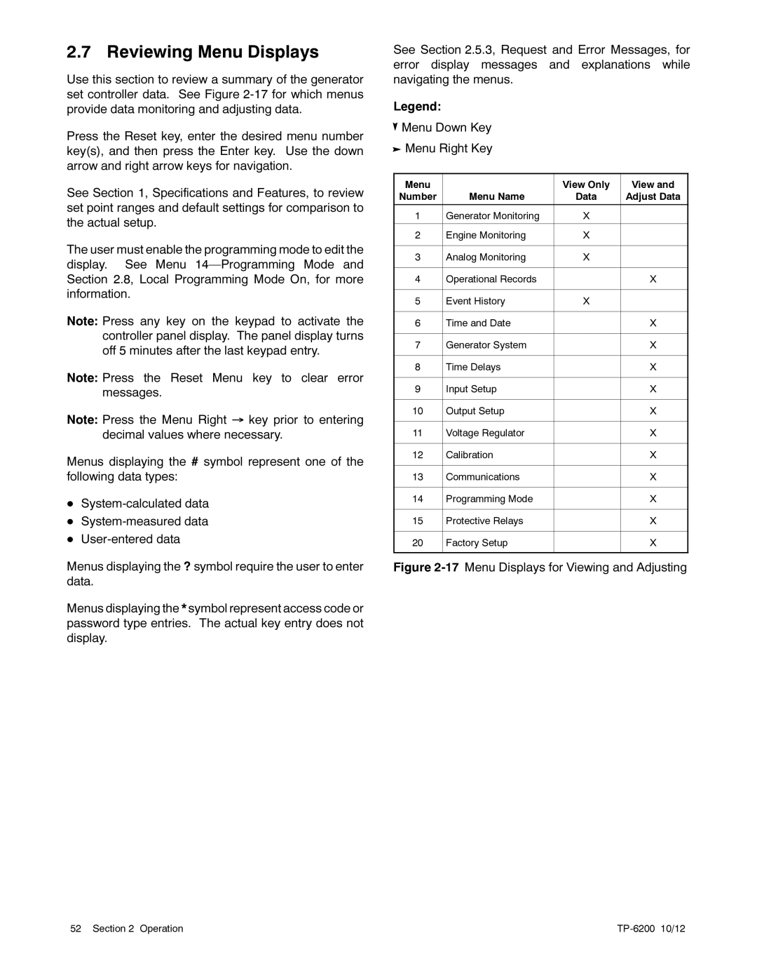
Legend:
![]() Menu Down Key
Menu Down Key
![]() Menu Right Key
Menu Right Key
Menu |
| View Only | View and |
Number | Menu Name | Data | Adjust Data |
|
|
|
|
1 | Generator Monitoring | X |
|
|
|
|
|
2 | Engine Monitoring | X |
|
|
|
|
|
3 | Analog Monitoring | X |
|
|
|
|
|
4 | Operational Records |
| X |
|
|
|
|
5 | Event History | X |
|
|
|
|
|
6 | Time and Date |
| X |
|
|
|
|
7 | Generator System |
| X |
|
|
|
|
8 | Time Delays |
| X |
|
|
|
|
9 | Input Setup |
| X |
|
|
|
|
10 | Output Setup |
| X |
|
|
|
|
11 | Voltage Regulator |
| X |
|
|
|
|
12 | Calibration |
| X |
|
|
|
|
13 | Communications |
| X |
|
|
|
|
14 | Programming Mode |
| X |
|
|
|
|
15 | Protective Relays |
| X |
|
|
|
|
20 | Factory Setup |
| X |
|
|
|
|
Figure 2-17 Menu Displays for Viewing and Adjusting
52 Section 2 Operation |
|