1 | 2 | 3 | 4 | 5 | 6 |
| 8 |
| 7 |
|
|
| |
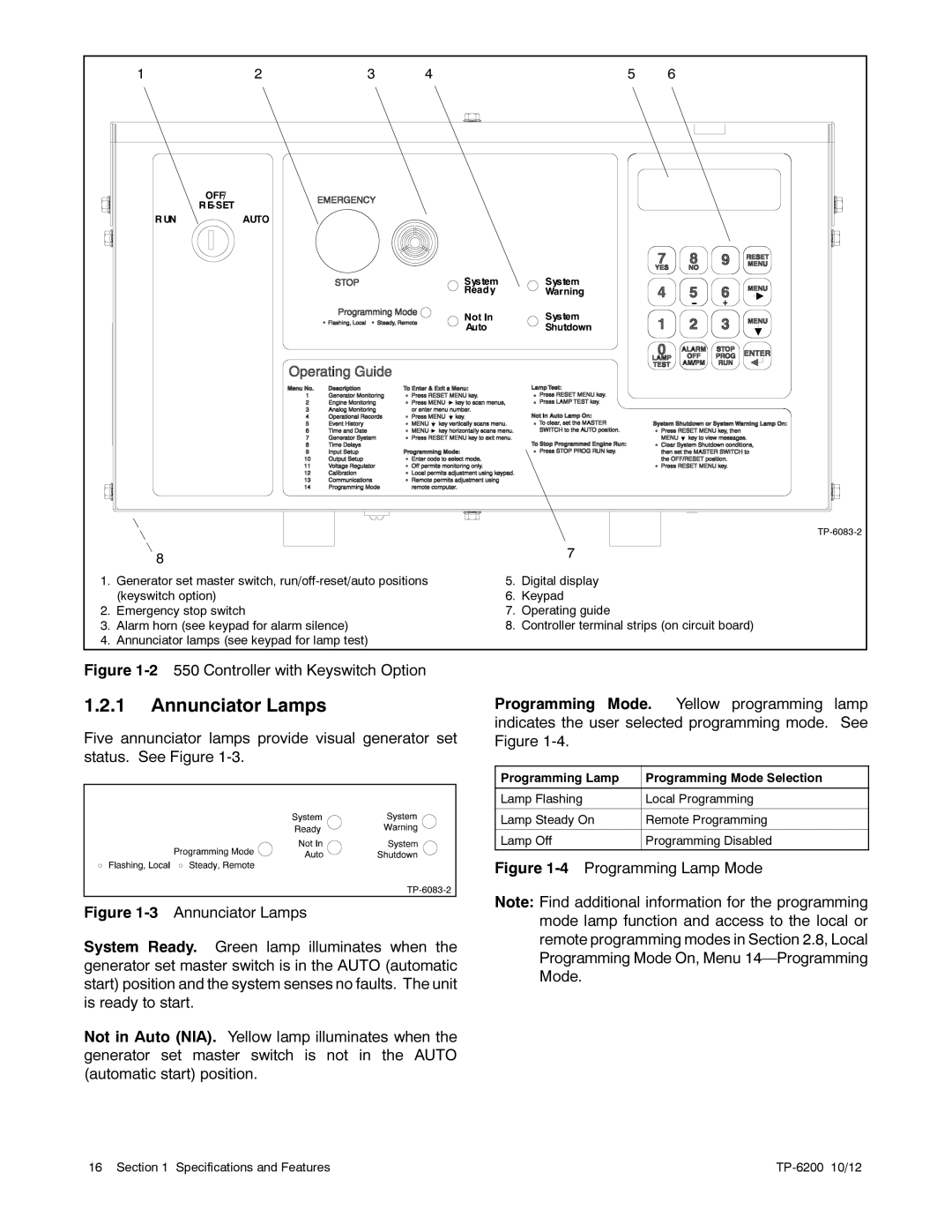
1. | Generator set master switch, | 5. | Digital display |
| (keyswitch option) | 6. | Keypad |
2. | Emergency stop switch | 7. | Operating guide |
3. | Alarm horn (see keypad for alarm silence) | 8. | Controller terminal strips (on circuit board) |
4. | Annunciator lamps (see keypad for lamp test) |
|
|
Figure 1-2 550 Controller with Keyswitch Option
1.2.1Annunciator Lamps
Five annunciator lamps provide visual generator set status. See Figure
Figure 1-3 Annunciator Lamps
System Ready. Green lamp illuminates when the generator set master switch is in the AUTO (automatic start) position and the system senses no faults. The unit is ready to start.
Not in Auto (NIA). Yellow lamp illuminates when the generator set master switch is not in the AUTO (automatic start) position.
Programming Mode. Yellow programming lamp indicates the user selected programming mode. See Figure 1-4.
Programming Lamp | Programming Mode Selection |
|
|
Lamp Flashing | Local Programming |
|
|
Lamp Steady On | Remote Programming |
|
|
Lamp Off | Programming Disabled |
|
|
Figure 1-4 Programming Lamp Mode
Note: Find additional information for the programming mode lamp function and access to the local or remote programming modes in Section 2.8, Local Programming Mode On, Menu
16 Section 1 Specifications and Features |
|