Factory-Defined Settings
|
|
|
|
| Relay |
|
|
|
|
| Inhibit |
|
Status Event | Refer |
|
| Driver | Alarm |
|
|
| Default | Time | Time | |
to |
|
| Output |
|
|
| Delay | Delay | ||||
or Fault | Menu | Digital Display |
| (RDO) | Horn | Lamp |
| Range Setting | Selection | (sec.) | (sec.) | |
|
|
|
|
|
|
|
|
|
|
|
| |
Voltage Raise |
|
|
|
|
|
|
|
|
|
|
| |
(see D19) |
|
|
|
|
|
|
|
|
|
|
| |
|
|
|
|
|
|
|
|
|
|
|
| |
Weak Battery | 10 | WEAK |
|
| Off | Warning |
|
| 60% of |
| 2 | |
|
|
| BATTERY |
|
|
|
|
|
| nominal |
|
|
|
|
|
|
|
|
|
|
|
|
|
| |
* | All models, except |
|
| ** NFPA applications |
|
|
| |||||
[ |
|
|
|
| [[ DDC/MTU engine with MDEC/ADEC |
|
| |||||
] |
|
|
|
| ]] FAA only |
|
|
|
| |||
w | Paralleling applications |
|
|
|
|
|
|
|
|
|
| |
|
|
|
|
|
|
|
|
|
|
|
|
|
| Refer to |
|
|
Calibration | Menu | Digital Display | Range Setting |
|
|
|
|
Voltage Adjustment | 11 | VOLT ADJ | ±10% of system voltage— |
|
|
| Version 2.10 |
|
|
| ±20% of system voltage— |
|
|
| Version 2.11 or higher |
|
|
|
|
Underfrequency Unload | 11 | FREQUENCY | 40 to 70 Hz |
Frequency Setpoint |
| SETPOINT |
|
|
|
|
|
Underfrequency Unload | 11 | SLOPE | |
Slope |
|
| volts per cycle |
|
|
|
|
Reactive Droop | 11 | VOLTAGE | |
|
| DROOP |
|
|
|
|
|
VAR Control | 11 | KVAR ADJ | 0 to rated kVAR generating |
|
|
| 0 to 35% of rated kVAR absorbing |
|
|
|
|
Power Factor (PF) Adjust | 11 | PF ADJ | 0.7 to 1.0 leading |
Control |
|
| 0.6 to 1.0 lagging |
|
|
|
|
Controller Gain | 11 | REGULATOR | |
|
| GAIN |
|
|
|
|
|
VAR/PF Gain or Utility | 11 | VAR/PF GAIN | |
Stability |
|
|
|
|
|
|
|
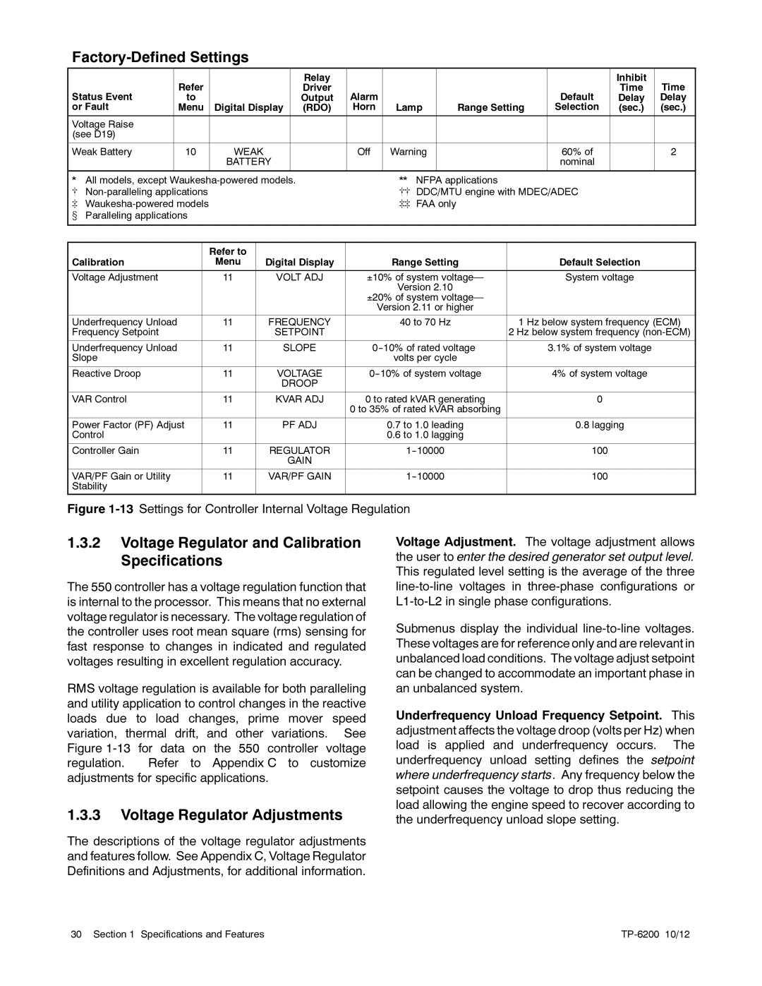
Figure 1-13 Settings for Controller Internal Voltage Regulation
Default Selection
System voltage
1 Hz below system frequency (ECM)
2 Hz below system frequency
3.1% of system voltage
4% of system voltage
0
0.8lagging
100
100
1.3.2Voltage Regulator and Calibration Specifications
The 550 controller has a voltage regulation function that is internal to the processor. This means that no external voltage regulator is necessary. The voltage regulation of the controller uses root mean square (rms) sensing for fast response to changes in indicated and regulated voltages resulting in excellent regulation accuracy.
RMS voltage regulation is available for both paralleling and utility application to control changes in the reactive loads due to load changes, prime mover speed variation, thermal drift, and other variations. See Figure
1.3.3Voltage Regulator Adjustments
The descriptions of the voltage regulator adjustments and features follow. See Appendix C, Voltage Regulator Definitions and Adjustments, for additional information.
Voltage Adjustment. The voltage adjustment allows the user to enter the desired generator set output level. This regulated level setting is the average of the three
Submenus display the individual
Underfrequency Unload Frequency Setpoint. This adjustment affects the voltage droop (volts per Hz) when load is applied and underfrequency occurs. The underfrequency unload setting defines the setpoint where underfrequency starts. Any frequency below the setpoint causes the voltage to drop thus reducing the load allowing the engine speed to recover according to the underfrequency unload slope setting.
30 Section 1 Specifications and Features |
|