2.8.3Menu 3—Analog Monitoring
Menu 3 provides the battery voltage and up to 7 user- defined analog monitoring items dependent upon the generator system.
The User Defined Desc display refers to a description entered into the controller using the PC software. This description remains as the display for future review until changed by the PC software user. The display has 20 characters maximum.
Analog Voltage Adjust. When the analog voltage adjust option is enabled (see Menu 11), analog input 7 is predefined as voltage adjust. The voltage of this input will define the adjustment from the setting in Menu 11, Voltage Regulator. The normal analog input range of 0.5 to 4.5 corresponds to a ±10% of system voltage. The
midpoint 2.5 volts corresponds to 0 volts offset. If there is no connection at analog input 7, no voltage adjust is recognized.
Note: If the analog display shows O/R (out of range), no input is connected.
Note: Some data require entry using a PC in the Remote Programming mode. See the monitor software operation manual for details.
Note: See Figure
Note: This menu is for monitoring only; no adjustments or user settings can be entered.
Menu 3—Analog Monitoring (ECM Engines)
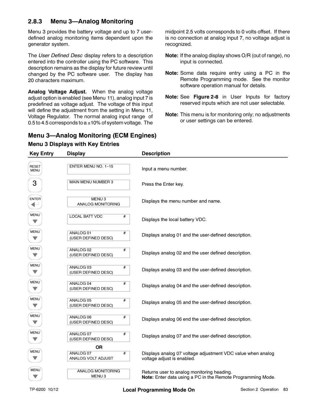
Menu 3 Displays with Key Entries
Key Entry | Display | Description |
|
|
|
ENTER MENU NO.
MAIN MENU NUMBER 3
MENU 3
ANALOG MONITORING
LOCAL BATT VDC | # |
|
|
|
|
ANALOG 01 | # |
(USER DEFINED DESC) |
|
|
|
|
|
ANALOG 02 | # |
(USER DEFINED DESC) |
|
|
|
ANALOG 03 | # |
(USER DEFINED DESC) |
|
|
|
|
|
ANALOG 04 | # |
(USER DEFINED DESC) |
|
|
|
ANALOG 05 | # |
(USER DEFINED DESC) |
|
|
|
|
|
ANALOG 06 | # |
(USER DEFINED DESC) |
|
|
|
|
|
ANALOG 07 | # |
(USER DEFINED DESC) |
|
OR |
|
|
|
ANALOG 07 | # |
ANALOG VOLT ADJUST |
|
|
|
ANALOG MONITORING
MENU 3
Input a menu number.
Press the Enter key.
Displays the menu number and name.
Displays the local battery VDC.
Displays analog 01 and the
Displays analog 02 and the user defined description.
Displays analog 03 and the
Displays analog 04 and the
Displays analog 05 and the
Displays analog 06 end the
Displays analog 07 and the
Displays analog 07 voltage adjustment VDC value when analog voltage adjust is enabled.
Returns user to analog monitoring heading.
Note: Enter data using a PC in the Remote Programming Mode.
| Local Programming Mode On | Section 2 Operation 83 |