3.4 Alternator Bearing Service
Have an authorized service distributor/dealer perform service.
3.4.120--300 kW Models
Replace the end bracket bearing every 10,000 hours of operation in standby and prime power applications. Service the bearing more frequently if the annual inspection indicates excessive rotor end play or bearing damage. Replace the tolerance ring, if equipped, following end bracket removal. The sealed end bracket bearing requires no additional lubrication.
3.4.2300--2250 kW Models with Single-Bearing Alternator
The alternator bearing requires lubrication at intervals specified in the generator set technical manual. Use Chevron SRI or equivalent antifriction,
3.4.31250 kW and Larger Models with
Refer to the generator set service manual for bearing maintenance information.
3.5 Diesel Fuel Systems
3.5.1Bleeding Air from Fuel System
Bleed air from the fuel system after fuel system maintenance, such as replacing the fuel filter(s). Use the hand prime pump kit, when equipped. The hand prime fuel pump eliminates the need for cranking the engine to bleed air from the fuel system.
Note: Bleed air from the fuel system according to the engine manufacturer’s instructions. Trapped air in the fuel system causes difficult starting and/or erratic engine operation.
Note: Correct any fuel leaks encountered during the priming procedure.
1.Place the fuel valves in the fuel system prime position. Close the fuel valve located between the pipe tee and the engine. Open the fuel valves on each side of the fuel prime pump. See Figure
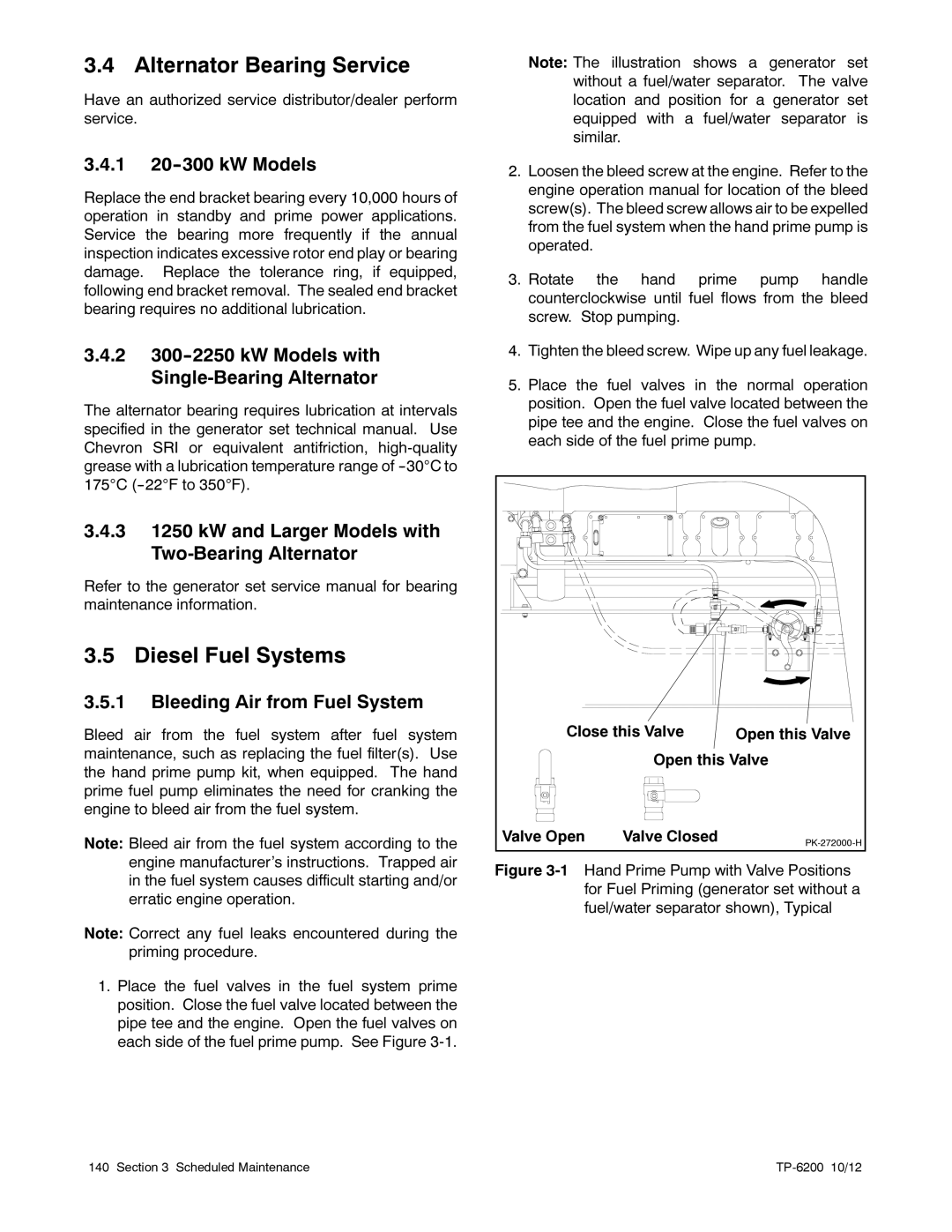
Note: The illustration shows a generator set without a fuel/water separator. The valve location and position for a generator set equipped with a fuel/water separator is similar.
2.Loosen the bleed screw at the engine. Refer to the engine operation manual for location of the bleed screw(s). The bleed screw allows air to be expelled from the fuel system when the hand prime pump is operated.
3.Rotate the hand prime pump handle counterclockwise until fuel flows from the bleed screw. Stop pumping.
4.Tighten the bleed screw. Wipe up any fuel leakage.
5.Place the fuel valves in the normal operation position. Open the fuel valve located between the pipe tee and the engine. Close the fuel valves on each side of the fuel prime pump.
Close this Valve | Open this Valve | |
| Open this Valve | |
Valve Open | Valve Closed | |
|
| |
Figure 3-1 Hand Prime Pump with Valve Positions for Fuel Priming (generator set without a fuel/water separator shown), Typical
140 Section 3 Scheduled Maintenance |
|