6.Replace the pressure cap.
7.Fill the coolant recovery tank to the low mark.
8.Operate generator set until the thermostat opens when the upper cooling system hose warms.
9.Stop the engine and allow it to cool.
10.Check and repair any coolant leaks.
11.Remove the pressure cap.
12.Add coolant to bring the coolant level to just below the overflow tube opening of the filler neck.
13.Replace the pressure cap.
14.Maintain the coolant level in the coolant recovery tank between the high and low marks.
Note: Air pockets often form in the engine water jacket when the coolant system is refilled. Check the coolant level in the coolant recovery tank after each generator set operation and add coolant as necessary until the coolant level stabilizes. Then check the coolant at the interval specified in the service schedule.
15.Reenergize the block heater, if equipped.
3.8Radiator Fan Bolt Retorque
Adapted from Service Bulletin
Check the radiator fan bolts after approximately 8 hours of operation and then recheck after each 100 hours of operation. This scheduled service is required on
Perform the scheduled service steps in the order shown.
Required Tools
DSocket wrench sets American Standard and Metric sizes
DTorque wrench, up to 203 Nm (150 ft. lb.)
Procedure
1.Place the generator set master switch in the OFF/ RESET position.
2.Disconnect the power to the battery charger, if equipped.
3.Disconnect the generator set engine starting battery(ies), negative
4.Remove the fan guards, screens, and covers as necessary to access the radiator fan hardware.
5.Inspect the blades for cracks or other damage. Verify that all hardware is present. Replace as needed.
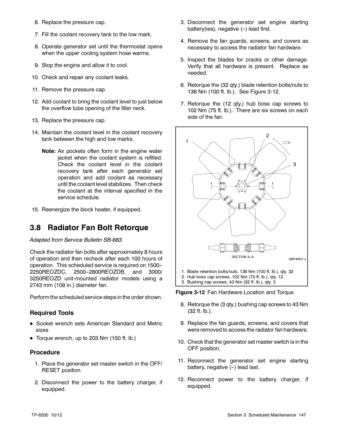
6.Retorque the (32 qty.) blade retention bolts/nuts to 136 Nm (100 ft. lb.). See Figure
7.Retorque the (12 qty.) hub boss cap screws to 102 Nm (75 ft. lb.). There are six screws on each side of the fan.
| 2 |
| 1 |
| 3 |
| SECTION |
| |
1. | Blade retention bolts/nuts, 136 Nm (100 ft. lb.), qty. 32 |
2. | Hub boss cap screws, 102 Nm (75 ft. lb.), qty. 12 |
3. | Bushing cap screws, 43 Nm (32 ft. lb.), qty. 3 |
Figure 3-12 Fan Hardware Location and Torque
8.Retorque the (3 qty.) bushing cap screws to 43 Nm (32 ft. lb.).
9.Replace the fan guards, screens, and covers that were removed to access the radiator fan hardware.
10.Check that the generator set master switch is in the OFF position.
11.Reconnect the generator set engine starting battery, negative (--) lead last.
12.Reconnect power to the battery charger, if equipped.
Section 3 Scheduled Maintenance 147 |