Appendix E Inputs and System Events by Application
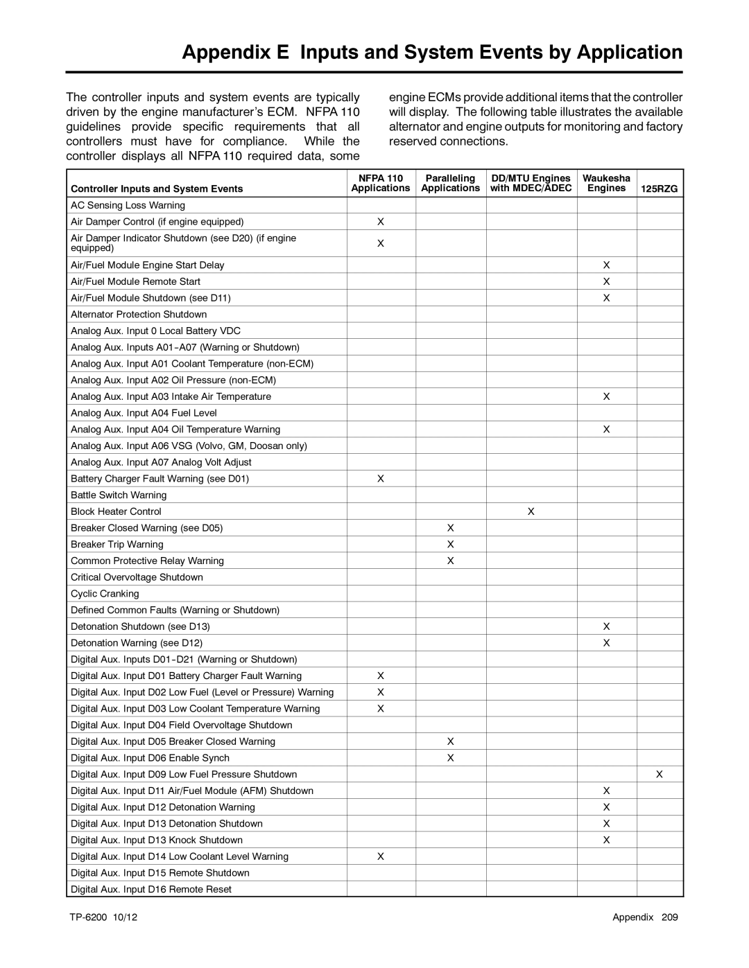
The controller inputs and system events are typically driven by the engine manufacturer’s ECM. NFPA 110 guidelines provide specific requirements that all controllers must have for compliance. While the controller displays all NFPA 110 required data, some
engine ECMs provide additional items that the controller will display. The following table illustrates the available alternator and engine outputs for monitoring and factory reserved connections.
| NFPA 110 | Paralleling | DD/MTU Engines | Waukesha |
|
Controller Inputs and System Events | Applications | Applications | with MDEC/ADEC | Engines | 125RZG |
|
|
|
|
|
|
AC Sensing Loss Warning |
|
|
|
|
|
|
|
|
|
|
|
Air Damper Control (if engine equipped) | X |
|
|
|
|
|
|
|
|
|
|
Air Damper Indicator Shutdown (see D20) (if engine | X |
|
|
|
|
equipped) |
|
|
|
| |
|
|
|
|
| |
|
|
|
|
|
|
Air/Fuel Module Engine Start Delay |
|
|
| X |
|
|
|
|
|
|
|
Air/Fuel Module Remote Start |
|
|
| X |
|
|
|
|
|
|
|
Air/Fuel Module Shutdown (see D11) |
|
|
| X |
|
|
|
|
|
|
|
Alternator Protection Shutdown |
|
|
|
|
|
|
|
|
|
|
|
Analog Aux. Input 0 Local Battery VDC |
|
|
|
|
|
|
|
|
|
|
|
Analog Aux. Inputs |
|
|
|
|
|
|
|
|
|
|
|
Analog Aux. Input A01 Coolant Temperature |
|
|
|
|
|
|
|
|
|
|
|
Analog Aux. Input A02 Oil Pressure |
|
|
|
|
|
|
|
|
|
|
|
Analog Aux. Input A03 Intake Air Temperature |
|
|
| X |
|
|
|
|
|
|
|
Analog Aux. Input A04 Fuel Level |
|
|
|
|
|
|
|
|
|
|
|
Analog Aux. Input A04 Oil Temperature Warning |
|
|
| X |
|
|
|
|
|
|
|
Analog Aux. Input A06 VSG (Volvo, GM, Doosan only) |
|
|
|
|
|
|
|
|
|
|
|
Analog Aux. Input A07 Analog Volt Adjust |
|
|
|
|
|
|
|
|
|
|
|
Battery Charger Fault Warning (see D01) | X |
|
|
|
|
|
|
|
|
|
|
Battle Switch Warning |
|
|
|
|
|
|
|
|
|
|
|
Block Heater Control |
|
| X |
|
|
|
|
|
|
|
|
Breaker Closed Warning (see D05) |
| X |
|
|
|
|
|
|
|
|
|
Breaker Trip Warning |
| X |
|
|
|
|
|
|
|
|
|
Common Protective Relay Warning |
| X |
|
|
|
|
|
|
|
|
|
Critical Overvoltage Shutdown |
|
|
|
|
|
|
|
|
|
|
|
Cyclic Cranking |
|
|
|
|
|
|
|
|
|
|
|
Defined Common Faults (Warning or Shutdown) |
|
|
|
|
|
|
|
|
|
|
|
Detonation Shutdown (see D13) |
|
|
| X |
|
|
|
|
|
|
|
Detonation Warning (see D12) |
|
|
| X |
|
|
|
|
|
|
|
Digital Aux. Inputs |
|
|
|
|
|
|
|
|
|
|
|
Digital Aux. Input D01 Battery Charger Fault Warning | X |
|
|
|
|
|
|
|
|
|
|
Digital Aux. Input D02 Low Fuel (Level or Pressure) Warning | X |
|
|
|
|
|
|
|
|
|
|
Digital Aux. Input D03 Low Coolant Temperature Warning | X |
|
|
|
|
|
|
|
|
|
|
Digital Aux. Input D04 Field Overvoltage Shutdown |
|
|
|
|
|
|
|
|
|
|
|
Digital Aux. Input D05 Breaker Closed Warning |
| X |
|
|
|
|
|
|
|
|
|
Digital Aux. Input D06 Enable Synch |
| X |
|
|
|
|
|
|
|
|
|
Digital Aux. Input D09 Low Fuel Pressure Shutdown |
|
|
|
| X |
|
|
|
|
|
|
Digital Aux. Input D11 Air/Fuel Module (AFM) Shutdown |
|
|
| X |
|
|
|
|
|
|
|
Digital Aux. Input D12 Detonation Warning |
|
|
| X |
|
|
|
|
|
|
|
Digital Aux. Input D13 Detonation Shutdown |
|
|
| X |
|
|
|
|
|
|
|
Digital Aux. Input D13 Knock Shutdown |
|
|
| X |
|
|
|
|
|
|
|
Digital Aux. Input D14 Low Coolant Level Warning | X |
|
|
|
|
|
|
|
|
|
|
Digital Aux. Input D15 Remote Shutdown |
|
|
|
|
|
|
|
|
|
|
|
Digital Aux. Input D16 Remote Reset |
|
|
|
|
|
| Appendix 209 |
