6.2 Accessory Connections
The 550 controller contains circuit boards equipped with terminal strip(s) for use in connecting a controller connection kit. Do not connect accessories directly to the controller terminal strip(s). Connect accessories to either a controller connection kit or a dry contact kit. Connect the dry contact kit(s) to the controller connection kit. Connect alarms, battery chargers, remote switches, and other accessories to the dry contact kit relay(s).
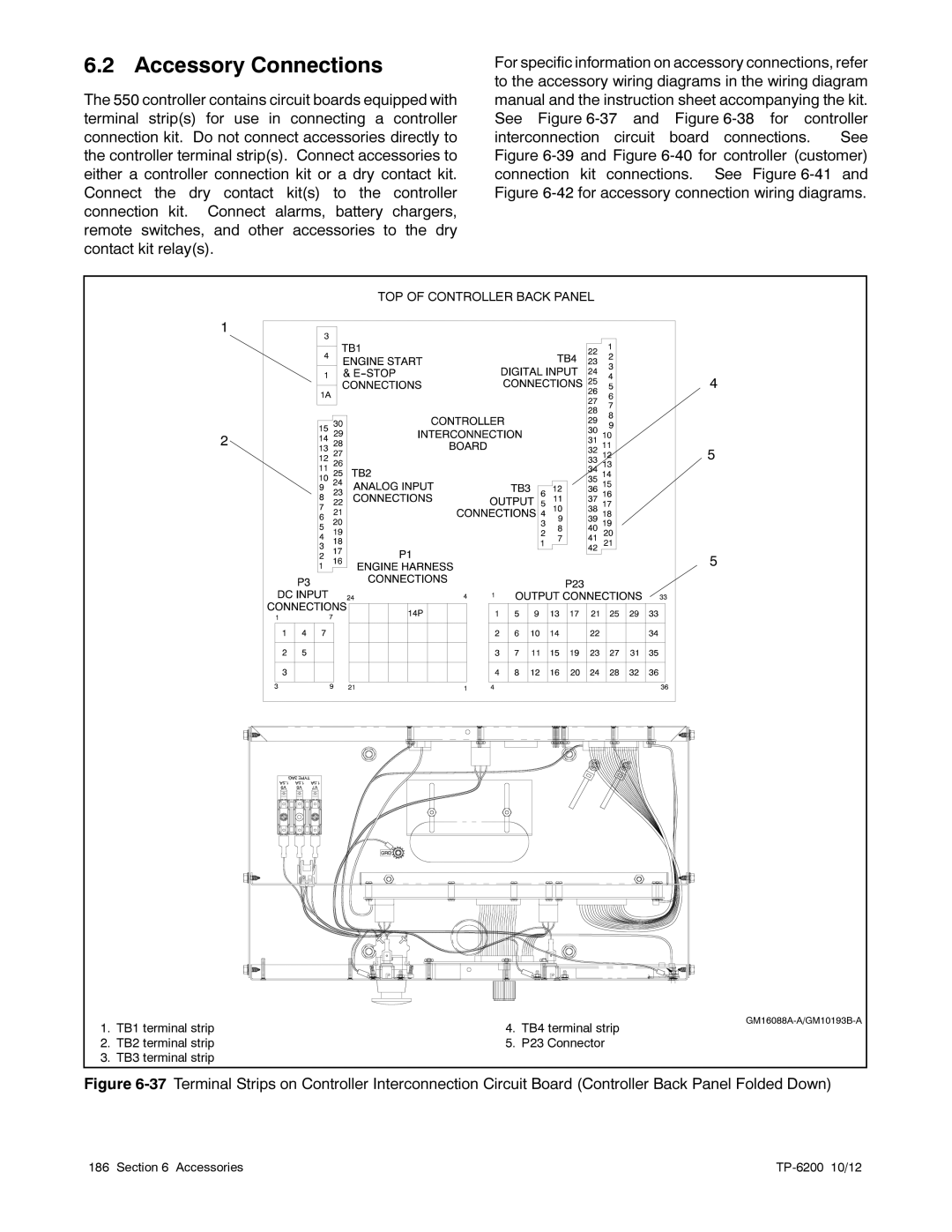
For specific information on accessory connections, refer to the accessory wiring diagrams in the wiring diagram manual and the instruction sheet accompanying the kit. See Figure
|
| TOP OF CONTROLLER BACK PANEL |
|
| 1 |
|
|
|
| 4 |
|
| 2 |
|
|
|
| 5 |
|
|
| 5 |
|
1. | TB1 terminal strip | ||
4. TB4 terminal strip |
| ||
2. | TB2 terminal strip | 5. P23 Connector |
|
3. | TB3 terminal strip |
|
|
Figure | |||
186 | Section 6 Accessories | 10/12 | |