Appendix B User-Defined Settings
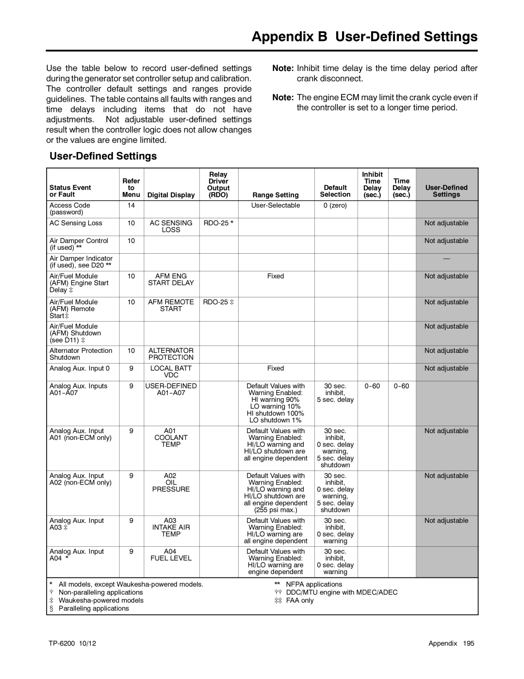
Use the table below to record
Note: Inhibit time delay is the time delay period after crank disconnect.
Note: The engine ECM may limit the crank cycle even if the controller is set to a longer time period.
User-Defined Settings
|
|
| Relay |
|
| Inhibit |
|
|
Status Event | Refer |
| Driver |
| Default | Time | Time | |
to |
| Output |
| Delay | Delay | |||
or Fault | Menu | Digital Display | (RDO) | Range Setting | Selection | (sec.) | (sec.) | Settings |
Access Code | 14 |
|
| 0 (zero) |
|
|
| |
(password) |
|
|
|
|
|
|
|
|
AC Sensing Loss | 10 | AC SENSING |
|
|
|
| Not adjustable | |
|
| LOSS |
|
|
|
|
|
|
Air Damper Control | 10 |
|
|
|
|
|
| Not adjustable |
(if used) ** |
|
|
|
|
|
|
|
|
Air Damper Indicator |
|
|
|
|
|
|
| — |
(if used), see D20 ** |
|
|
|
|
|
|
|
|
Air/Fuel Module | 10 | AFM ENG |
| Fixed |
|
|
| Not adjustable |
(AFM) Engine Start |
| START DELAY |
|
|
|
|
|
|
Delay ] |
|
|
|
|
|
|
|
|
|
|
|
|
|
|
|
|
|
Air/Fuel Module | 10 | AFM REMOTE |
|
|
|
| Not adjustable | |
(AFM) Remote |
| START |
|
|
|
|
|
|
Start ] |
|
|
|
|
|
|
|
|
Air/Fuel Module |
|
|
|
|
|
|
| Not adjustable |
(AFM) Shutdown |
|
|
|
|
|
|
|
|
(see D11) ] |
|
|
|
|
|
|
|
|
Alternator Protection | 10 | ALTERNATOR |
|
|
|
|
| Not adjustable |
Shutdown |
| PROTECTION |
|
|
|
|
|
|
Analog Aux. Input 0 | 9 | LOCAL BATT |
| Fixed |
|
|
| Not adjustable |
|
| VDC |
|
|
|
|
|
|
Analog Aux. Inputs | 9 |
|
| Default Values with | 30 sec. |
| ||
|
| Warning Enabled: | inhibit, |
|
|
| ||
|
|
|
| HI warning 90% | 5 sec. delay |
|
|
|
|
|
|
| LO warning 10% |
|
|
|
|
|
|
|
| HI shutdown 100% |
|
|
|
|
|
|
|
| LO shutdown 1% |
|
|
|
|
Analog Aux. Input | 9 | A01 |
| Default Values with | 30 sec. |
|
| Not adjustable |
A01 |
| COOLANT |
| Warning Enabled: | inhibit, |
|
|
|
|
| TEMP |
| HI/LO warning and | 0 sec. delay |
|
|
|
|
|
|
| HI/LO shutdown are | warning, |
|
|
|
|
|
|
| all engine dependent | 5 sec. delay |
|
|
|
|
|
|
|
| shutdown |
|
|
|
Analog Aux. Input | 9 | A02 |
| Default Values with | 30 sec. |
|
| Not adjustable |
A02 |
| OIL |
| Warning Enabled: | inhibit, |
|
|
|
|
| PRESSURE |
| HI/LO warning and | 0 sec. delay |
|
|
|
|
|
|
| HI/LO shutdown are | warning, |
|
|
|
|
|
|
| all engine dependent | 5 sec. delay |
|
|
|
|
|
|
| (255 psi max.) | shutdown |
|
|
|
Analog Aux. Input | 9 | A03 |
| Default Values with | 30 sec. |
|
| Not adjustable |
A03 ] |
| INTAKE AIR |
| Warning Enabled: | inhibit, |
|
|
|
|
| TEMP |
| HI/LO warning are | 0 sec. delay |
|
|
|
|
|
|
| all engine dependent | warning |
|
|
|
Analog Aux. Input | 9 | A04 |
| Default Values with | 30 sec. |
|
|
|
A04 * |
| FUEL LEVEL |
| Warning Enabled: | inhibit, |
|
|
|
|
|
|
| HI/LO warning are | 0 sec. delay |
|
|
|
|
|
|
| engine dependent | warning |
|
|
|
|
|
|
|
|
|
|
|
|
* | All models, except | ** | NFPA applications |
[ | [[ | DDC/MTU engine with MDEC/ADEC | |
] | ]] | FAA only | |
w | Paralleling applications |
|
|
| Appendix 195 |
