156 Section 4 Troubleshooting
TP-6200 10/12
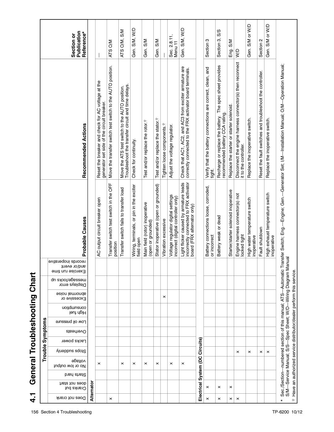
4.1 | General Troubleshooting Chart |
|
|
| |||||||||||
|
|
|
|
|
|
|
|
|
|
|
|
|
|
|
|
|
|
|
| Trouble Symptoms |
|
|
|
|
|
|
| ||||
|
|
|
|
|
|
|
|
|
|
|
|
|
|
|
|
Doesnot crank |
| Cranksbut doesnot start | Startshard | orNolow output voltage | Stopssuddenly | Lackspower | Overheats | Lowoil pressure | Highfuel consumption | Excessiveor abnormalnoise | Displayserror message/locksup | Exerciserun time and/orevent recordsinoperative | Probable Causes | Recommended Actions | Reference* |
|
|
|
|
|
|
|
|
|
|
|
|
|
|
| Section or |
|
|
|
|
|
|
|
|
|
|
|
|
|
|
| Publication |
|
|
|
|
|
|
|
|
|
|
|
|
|
|
| |
Alternator |
|
|
|
|
|
|
|
|
|
|
|
|
| ||
|
|
|
|
|
|
|
|
|
|
|
|
|
|
|
|
|
|
|
| x |
|
|
|
|
|
|
|
| AC output circuit breaker open | Reset the breaker and check for AC voltage at the | — |
|
|
|
|
|
|
|
|
|
|
|
|
|
| generator set side of the circuit breaker. |
|
|
|
|
|
|
|
|
|
|
|
|
|
|
|
|
|
x |
|
|
|
|
|
|
|
|
|
|
|
| Transfer switch test switch in the OFF | Move the transfer switch test switch to the AUTO position. | ATS O/M |
|
|
|
|
|
|
|
|
|
|
|
|
| position |
|
|
|
|
|
|
|
|
|
|
|
|
|
|
|
|
|
|
|
|
|
| x |
|
|
|
|
|
|
|
| Transfer switch fails to transfer load | Move the ATS test switch to the AUTO position. | ATS O/M, S/M |
|
|
|
|
|
|
|
|
|
|
|
|
|
| Troubleshoot the transfer circuit and time delays. |
|
|
|
|
|
|
|
|
|
|
|
|
|
|
|
|
|
|
|
|
| x |
|
|
|
|
|
|
|
| Wiring, terminals, or pin in the exciter | Check for continuity. | Gen. S/M, W/D |
|
|
|
|
|
|
|
|
|
|
|
|
| field open |
|
|
|
|
|
|
|
|
|
|
|
|
|
|
|
|
|
|
|
|
|
| x |
|
|
|
|
|
|
|
| Main field (rotor) inoperative | Test and/or replace the rotor.[ | Gen. S/M |
|
|
|
|
|
|
|
|
|
|
|
|
| (open or grounded) |
|
|
|
|
|
|
|
|
|
|
|
|
|
|
|
|
|
|
|
|
|
| x |
|
|
|
|
|
|
|
| Stator inoperative (open or grounded) | Test and/or replace the stator.[ | Gen. S/M |
|
|
|
|
|
|
|
|
|
|
|
|
|
|
|
|
|
|
|
|
|
|
|
|
|
| x |
|
| Vibration excessive | Tighten loose components.[ | — |
|
|
|
|
|
|
|
|
|
|
|
|
|
|
|
|
|
|
|
| x |
|
|
|
|
|
|
|
| Voltage regulator digital settings | Adjust the voltage regulator. | Sec. 2.8.11, |
|
|
|
|
|
|
|
|
|
|
|
|
| incorrect (digital controller only) |
| Menu 11 |
|
|
|
|
|
|
|
|
|
|
|
|
|
|
|
|
|
|
|
| x |
|
|
|
|
|
|
|
| Light flicker caused by armature leads | Check that AC1, AC2, and AC3 from exciter armature are | Gen. S/M, W/D |
|
|
|
|
|
|
|
|
|
|
|
|
| incorrectly connected to FRX activator | correctly connected to the FRX activator board terminals. |
|
|
|
|
|
|
|
|
|
|
|
|
|
| board (FRX alternator only) |
|
|
|
|
|
|
|
|
|
|
|
|
|
|
|
|
| |
Electrical System (DC Circuits) |
|
|
|
|
|
|
|
|
| ||||||
|
|
|
|
|
|
|
|
|
|
|
|
|
|
| |
x |
| x |
|
|
|
|
|
|
|
|
|
| Battery connections loose, corroded, | Verify that the battery connections are correct, clean, and | Section 3 |
|
|
|
|
|
|
|
|
|
|
|
|
| or incorrect | tight. |
|
|
|
|
|
|
|
|
|
|
|
|
|
|
|
|
|
x |
| x |
|
|
|
|
|
|
|
|
|
| Battery weak or dead | Recharge or replace the battery. The spec sheet provides | Section 3, S/S |
|
|
|
|
|
|
|
|
|
|
|
|
|
| recommended battery CCA rating. |
|
|
|
|
|
|
|
|
|
|
|
|
|
|
|
|
|
x |
| x |
|
|
|
|
|
|
|
|
|
| Starter/starter solenoid inoperative | Replace the starter or starter solenoid. | Eng. S/M |
|
|
|
|
|
|
|
|
|
|
|
|
|
|
|
|
x |
|
|
|
| x |
|
|
|
|
|
|
| Engine harness connector(s) not | Disconnect the engine harness connector(s) then reconnect | W/D |
|
|
|
|
|
|
|
|
|
|
|
|
| locked tight | it to the controller. |
|
|
|
|
|
|
|
|
|
|
|
|
|
|
|
|
|
|
|
|
|
| x |
|
|
|
|
|
|
| High water temperature switch | Replace the inoperative switch. | Gen. S/M or W/D |
|
|
|
|
|
|
|
|
|
|
|
|
| inoperative |
|
|
|
|
|
|
|
|
|
|
|
|
|
|
|
|
|
|
|
|
|
|
| x |
|
|
|
|
|
|
| Fault shutdown | Reset the fault switches and troubleshoot the controller. | Section 2 |
|
|
|
|
|
|
|
|
|
|
|
|
|
|
|
|
|
|
|
|
| x |
|
|
|
|
|
|
| High exhaust temperature switch | Replace the inoperative switch. | Gen. S/M or W/D |
|
|
|
|
|
|
|
|
|
|
|
|
| inoperative |
|
|
|
|
|
|
|
|
|
|
|
|
|
|
|
|
|
|
*
[ Have an authorized service distributor/dealer perform this service.