2.7.5Menu 5—Event History
Menu 5 stores and displays the times and dates of up to 100 stored status, warning, and shutdown events. After the first 100 events, each additional new event replaces the oldest event. See Menu
Menu 5 Overview
MENU 5
EVENT HISTORY
(MESSAGE TEXT)
##:## AM/PM |
SCROLL THROUGH 100 (max.)
STORED EVENTS
2.7.6Menu 6—Time and Date
Menu 6 shows the internal clock time and calendar date. The controller uses the set clock time to determine exercise run time and event records. The time and date are valid as long as the controller power (starting battery) remains connected.
The user must enable the programming mode to edit the display.
See Section 2.8.6 to change the time and/or date.
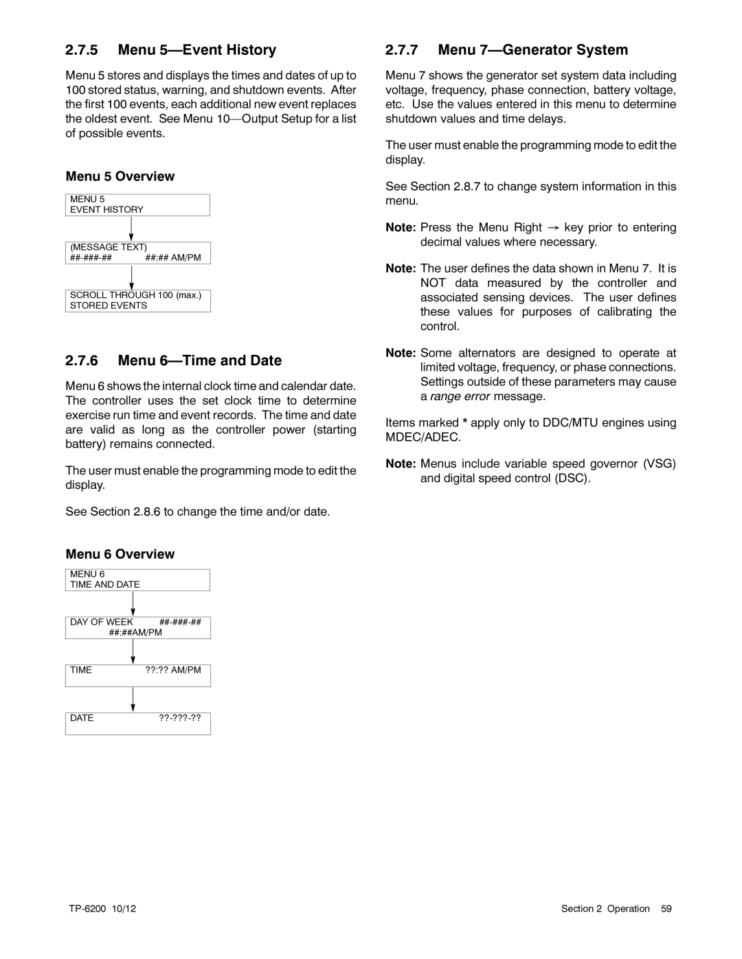
Menu 6 Overview
MENU 6
TIME AND DATE
DAY OF WEEK | |
##:##AM/PM | |
|
|
|
|
TIME | ??:?? AM/PM |
|
|
|
|
|
|
DATE | |
|
|
2.7.7Menu 7—Generator System
Menu 7 shows the generator set system data including voltage, frequency, phase connection, battery voltage, etc. Use the values entered in this menu to determine shutdown values and time delays.
The user must enable the programming mode to edit the display.
See Section 2.8.7 to change system information in this menu.
Note: Press the Menu Right → key prior to entering decimal values where necessary.
Note: The user defines the data shown in Menu 7. It is NOT data measured by the controller and associated sensing devices. The user defines these values for purposes of calibrating the control.
Note: Some alternators are designed to operate at limited voltage, frequency, or phase connections. Settings outside of these parameters may cause a range error message.
Items marked * apply only to DDC/MTU engines using MDEC/ADEC.
Note: Menus include variable speed governor (VSG) and digital speed control (DSC).
| Section 2 Operation 59 |