13.Place the generator set master switch to the RUN position to start the generator set. Refer to the respective generator set operation manual as needed.
14.Listen and observe the fan operation.
15.Immediately shut down the generator set if abnormal noise or fan assembly vibration is observed. Correct the problem and go back to step 13.
16.After several minutes of generator set operation without abnormal noise or vibration, shut down the generator set by placing the generator set master switch to the OFF/RESET position.
3.9Radiator Expansion Joint Loosening—Initial Setup Only
Loosen the radiator expansion joint nuts on
4
1
2
3
1. Air flow | |
|
2.Expansion joint nuts for rear tank, left side
3.Expansion joint nuts for front tank, left side
4.Top front of radiator
Figure 3-13 Expansion Joint Nuts, Top Left Side of Radiator, Typical
3.10Radiator Fan Bearing Lubrication
The following procedure applies only to 1200 kW and larger generator sets. Lubricate the radiator fan shaft and idler shaft bearings at every engine oil change to avoid bearing damage. Lubricate the bearings every 200 hours of operation when the generator set runs in ambient temperatures below 29°C (85°F) or when the generator set runs in a dusty and/or humid environment.
Lubrication and Drive Belt Adjustment Procedure
Lubricate the fan shaft and idler shaft bearings with a
1.Place the generator set master switch in the OFF/RESET position.
2.Disconnect the generator set engine starting battery(ies), negative
3.Remove the belt guards to expose the fan shaft and idler shaft bearings.
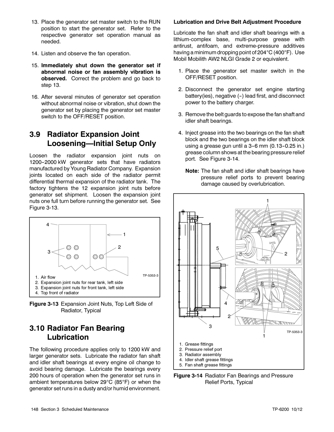
4.Inject grease into the two bearings on the fan shaft block and the two bearings on the idler shaft block using a grease gun until a
Note: The fan shaft and idler shaft bearings have pressure relief ports to prevent bearing damage caused by overlubrication.
| 1 |
| 5 |
| 2 |
| 4 |
| 2 |
| 3 |
| |
| 1 |
1. | Grease fittings |
2. | Pressure relief port |
3. | Radiator assembly |
4. | Idler shaft grease fittings |
5. | Fan shaft grease fittings |
Figure 3-14 Radiator Fan Bearings and Pressure Relief Ports, Typical
148 Section 3 Scheduled Maintenance |
|