Section 1 Specifications and Features
1.1 Introduction
The spec sheets for each generator set provide model- specific generator and engine information. The controller spec sheet provides specifications for this controller. Refer to the respective spec sheet for data not supplied in this manual. Consult the generator set service manual, installation manual, engine operation manual, and engine service manual for additional specifications.
1.2 Controller Features
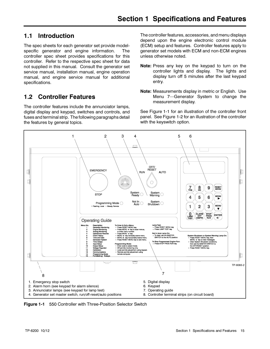
The controller features include the annunciator lamps, digital display and keypad, switches and controls, and fuses and terminal strip. The following paragraphs detail the features by general topics.
The controller features, accessories, and menu displays depend upon the engine electronic control module (ECM) setup and features. Controller features apply to generator set models with ECM and
Note: Press any key on the keypad to turn on the controller lights and display. The lights and display turn off 5 minutes after the last keypad entry.
Note: Measurements display in metric or English. Use Menu
See Figure
1 | 2 | 3 | 4 | 5 | 6 |
| 8 |
| 7 |
|
|
| |
1. | Emergency stop switch | 5. | Digital display |
2. | Alarm horn (see keypad for alarm silence) | 6. | Keypad |
3. | Annunciator lamps (see keypad for lamp test) | 7. | Operating guide |
4. | Generator set master switch, | 8. | Controller terminal strips (on circuit board) |
Figure 1-1 550 Controller with Three-Position Selector Switch
Section 1 Specifications and Features 15 |
