3.5.2Subbase Fuel Day Tank Electronic Control Module (ECM)
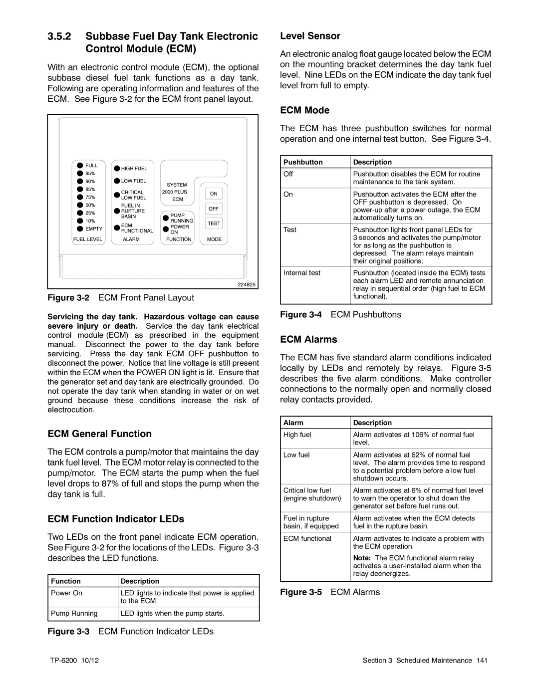
With an electronic control module (ECM), the optional subbase diesel fuel tank functions as a day tank. Following are operating information and features of the ECM. See Figure
224825 |
Figure 3-2 ECM Front Panel Layout
Servicing the day tank. Hazardous voltage can cause severe injury or death. Service the day tank electrical control module (ECM) as prescribed in the equipment manual. Disconnect the power to the day tank before servicing. Press the day tank ECM OFF pushbutton to disconnect the power. Notice that line voltage is still present within the ECM when the POWER ON light is lit. Ensure that the generator set and day tank are electrically grounded. Do not operate the day tank when standing in water or on wet ground because these conditions increase the risk of electrocution.
ECM General Function
The ECM controls a pump/motor that maintains the day tank fuel level. The ECM motor relay is connected to the pump/motor. The ECM starts the pump when the fuel level drops to 87% of full and stops the pump when the day tank is full.
ECM Function Indicator LEDs
Two LEDs on the front panel indicate ECM operation. See Figure
Function | Description |
|
|
Power On | LED lights to indicate that power is applied |
| to the ECM. |
|
|
Pump Running | LED lights when the pump starts. |
|
|
Figure 3-3 ECM Function Indicator LEDs
Level Sensor
An electronic analog float gauge located below the ECM on the mounting bracket determines the day tank fuel level. Nine LEDs on the ECM indicate the day tank fuel level from full to empty.
ECM Mode
The ECM has three pushbutton switches for normal operation and one internal test button. See Figure
Pushbutton | Description |
|
|
Off | Pushbutton disables the ECM for routine |
| maintenance to the tank system. |
|
|
On | Pushbutton activates the ECM after the |
| OFF pushbutton is depressed. On |
| |
| automatically turns on. |
|
|
Test | Pushbutton lights front panel LEDs for |
| 3 seconds and activates the pump/motor |
| for as long as the pushbutton is |
| depressed. The alarm relays maintain |
| their original positions. |
|
|
Internal test | Pushbutton (located inside the ECM) tests |
| each alarm LED and remote annunciation |
| relay in sequential order (high fuel to ECM |
| functional). |
|
|
Figure 3-4 ECM Pushbuttons
ECM Alarms
The ECM has five standard alarm conditions indicated locally by LEDs and remotely by relays. Figure
Alarm | Description |
|
|
High fuel | Alarm activates at 106% of normal fuel |
| level. |
|
|
Low fuel | Alarm activates at 62% of normal fuel |
| level. The alarm provides time to respond |
| to a potential problem before a low fuel |
| shutdown occurs. |
|
|
Critical low fuel | Alarm activates at 6% of normal fuel level |
(engine shutdown) | to warn the operator to shut down the |
| generator set before fuel runs out. |
|
|
Fuel in rupture | Alarm activates when the ECM detects |
basin, if equipped | fuel in the rupture basin. |
|
|
ECM functional | Alarm activates to indicate a problem with |
| the ECM operation. |
| Note: The ECM functional alarm relay |
| activates a |
| relay deenergizes. |
|
|
Figure 3-5 ECM Alarms
Section 3 Scheduled Maintenance 141 |