2.8.12 Menu 12—Calibration
Menu 12 provides the calibration of the voltage and current sensing logic. Changing the system voltage or replacing the main logic control circuit board requires a calibration adjustment.
The user must enable the programming mode to edit the display.
Connect a meter with a minimum accuracy of 1% to the generator set output leads to calibrate the
Reduce the voltage regulator gain using Menu 11, Voltage Regulator until the voltage is stable prior to calibration.
The user must scale the analog input value in order to calculate the low/high warning and shutdown analog values based on a
ECM engines have
inputs
Analog Input
Note: For VSG on Analog Aux. Input 06 calibrate: Volvo: 0.5V=1250; 4.5V=8750 GM/Doosan at 60 Hz: 0.5V=2375; 4.5V=2625 GM/Doosan at 50 Hz: 4.5V=2327; 4.5V=2624
Analog input A07 is the voltage adjustment for paralleling applications only. This input adjusts the input up or down from the value entered in Menu 11, Voltage Regulator. Calibration is not necessary.
Note: Press the Menu Right → key prior to entering decimal values where necessary.
Changes to the generator set system parameters causes a CHECK CALIBRATION display message. If the generator set system parameters are changed, verify the controller display calibration by comparing the results to a known measured value.
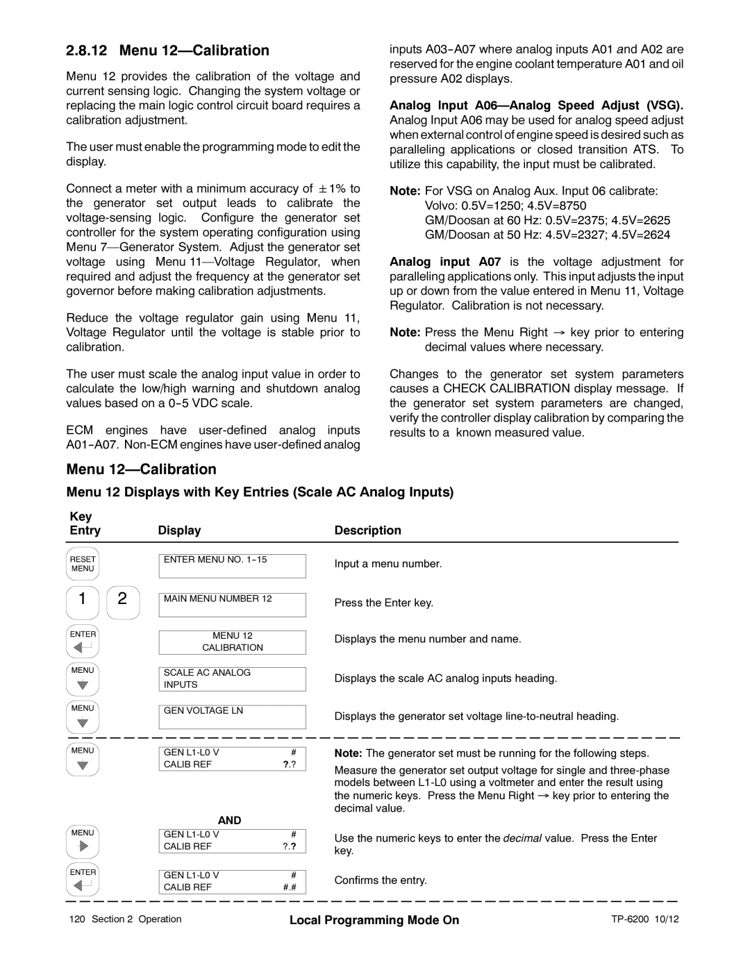
Menu 12—Calibration
Menu 12 Displays with Key Entries (Scale AC Analog Inputs)
Key |
|
|
Entry | Display | Description |
ENTER MENU NO.
MAIN MENU NUMBER 12
MENU 12
CALIBRATION
SCALE AC ANALOG
INPUTS
GEN VOLTAGE LN
GEN | # |
CALIB REF | ?.? |
|
|
AND
| GEN | # |
|
|
| ||||||||||||||||||
| CALIB REF | ?.? |
|
|
| ||||||||||||||||||
|
|
|
|
|
|
|
|
|
|
|
|
|
|
|
|
|
|
|
|
|
|
|
|
| GEN | # |
|
|
| ||||||||||||||||||
| CALIB REF | #.# |
|
|
| ||||||||||||||||||
|
|
|
|
|
|
|
|
|
|
|
|
|
|
|
|
|
|
|
|
|
|
|
|
|
|
|
|
|
|
|
|
|
|
|
|
|
|
|
|
|
|
|
|
|
|
|
|
Input a menu number.
Press the Enter key.
Displays the menu number and name.
Displays the scale AC analog inputs heading.
Displays the generator set voltage
Note: The generator set must be running for the following steps.
Measure the generator set output voltage for single and
Use the numeric keys to enter the decimal value. Press the Enter key.
Confirms the entry.
120 Section 2 Operation | Local Programming Mode On |
|