3.5.3Subbase Inner Fuel Tank Alarm
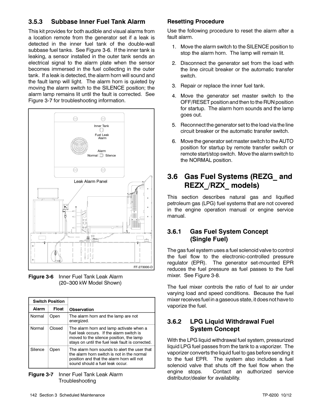
This kit provides for both audible and visual alarms from a location remote from the generator set if a leak is detected in the inner fuel tank of the
Inner Tank | |
Fuel Leak | |
| Alarm |
Alarm | |
Normal | Silence |
Leak Alarm Panel | |
| |
Figure 3-6 Inner Fuel Tank Leak Alarm (20--300 kW Model Shown)
Switch Position |
| |
|
|
|
Alarm | Float | Observation |
|
|
|
Normal | Open | The alarm horn and the lamp are not |
|
| energized. |
|
|
|
Normal | Closed | The alarm horn and lamp activate when a |
|
| fuel leak occurs. If the alarm switch is |
|
| moved to the silence position, the lamp |
|
| stays on until the fuel leak fault is corrected. |
|
|
|
Silence | Open | The alarm horn sounds to alert the user that |
|
| the alarm horn switch is not in the normal |
|
| position and that the alarm horn will not |
|
| sound should a fuel leak occur. |
|
|
|
Figure 3-7 Inner Fuel Tank Leak Alarm
Troubleshooting
Resetting Procedure
Use the following procedure to reset the alarm after a fault alarm.
1.Move the alarm switch to the SILENCE position to stop the alarm horn. The lamp will remain lit.
2.Disconnect the generator set from the load with the line circuit breaker or the automatic transfer switch.
3.Repair or replace the inner fuel tank.
4.Move the generator set master switch to the OFF/RESET position and then to the RUN position for startup. The alarm horn sounds and the lamp goes out.
5.Reconnect the generator set to the load via the line circuit breaker or the automatic transfer switch.
6.Move the generator set master switch to the AUTO position for startup by remote transfer switch or remote start/stop switch. Move the alarm switch to the NORMAL position.
3.6Gas Fuel Systems (REZG_ and REZX_/RZX_ models)
This section describes natural gas and liquified petroleum gas (LPG) fuel systems that are not covered in the engine operation manual or engine service manual.
3.6.1Gas Fuel System Concept (Single Fuel)
The gas fuel system uses a fuel solenoid valve to control the fuel flow to the
The fuel mixer controls the ratio of fuel to air under varying load and speed conditions. Because the fuel mixer receives fuel in a gaseous state, it does not have to vaporize the fuel.
3.6.2LPG Liquid Withdrawal Fuel System Concept
With the LPG liquid withdrawal fuel system, pressurized liquid LPG fuel passes from the tank to a vaporizer. The vaporizer converts the liquid fuel to gas before sending it to the fuel EPR. The system also includes a fuel solenoid valve that shuts off the fuel flow when the engine stops. Contact an authorized service distributor/dealer for availability.
142 Section 3 Scheduled Maintenance |
|