1.2.2Digital Display and Keypad
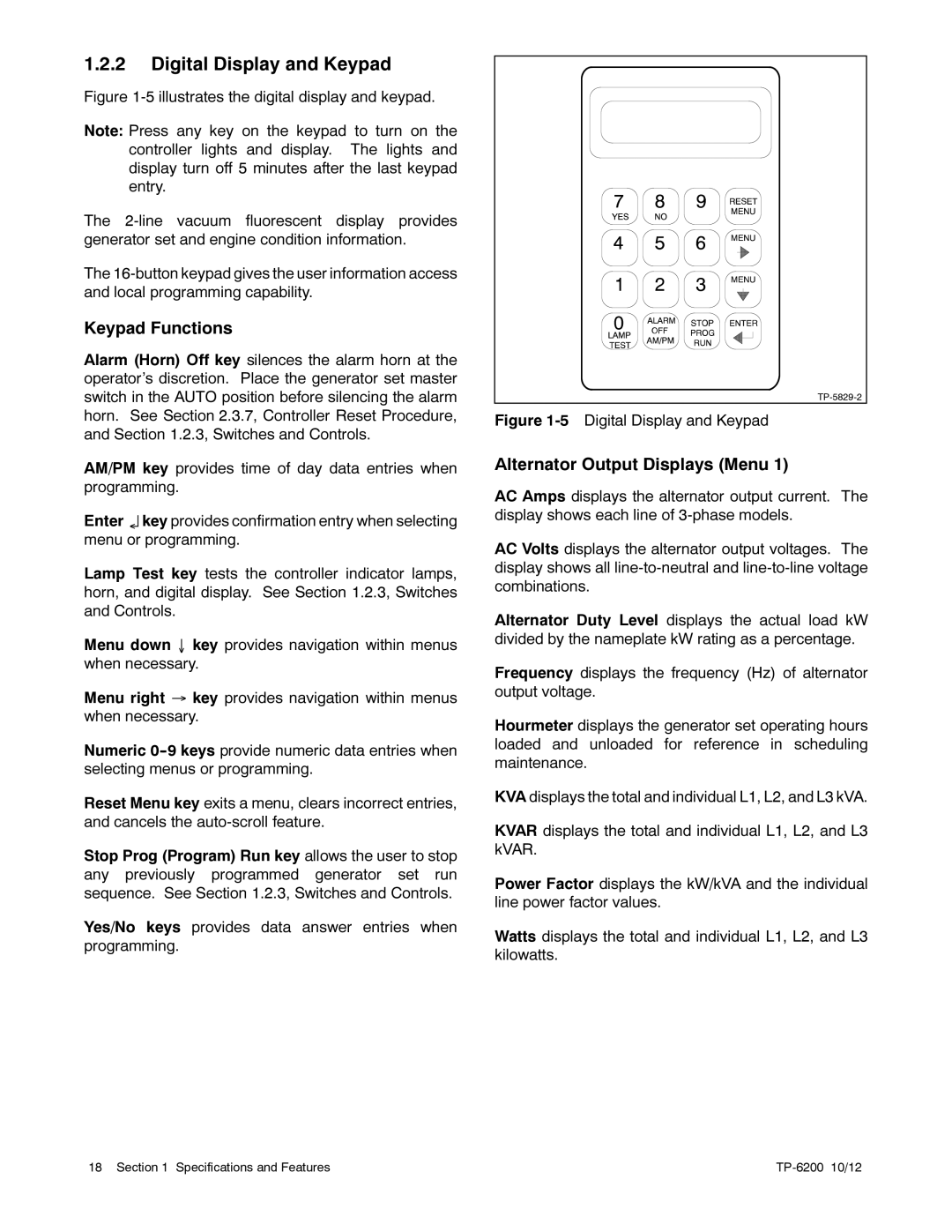
Figure 1-5 illustrates the digital display and keypad.
Note: Press any key on the keypad to turn on the controller lights and display. The lights and display turn off 5 minutes after the last keypad entry.
The 2-line vacuum fluorescent display provides generator set and engine condition information.
The 16-button keypad gives the user information access and local programming capability.
Keypad Functions
Alarm (Horn) Off key silences the alarm horn at the operator’s discretion. Place the generator set master switch in the AUTO position before silencing the alarm horn. See Section 2.3.7, Controller Reset Procedure, and Section 1.2.3, Switches and Controls.
AM/PM key provides time of day data entries when programming.
Enter ↵ key provides confirmation entry when selecting menu or programming.
Lamp Test key tests the controller indicator lamps, horn, and digital display. See Section 1.2.3, Switches and Controls.
Menu down ↓ key provides navigation within menus when necessary.
Menu right → key provides navigation within menus when necessary.
Numeric
Reset Menu key exits a menu, clears incorrect entries, and cancels the
Stop Prog (Program) Run key allows the user to stop any previously programmed generator set run sequence. See Section 1.2.3, Switches and Controls.
Yes/No keys provides data answer entries when programming.
Figure 1-5 Digital Display and Keypad
Alternator Output Displays (Menu 1)
AC Amps displays the alternator output current. The display shows each line of
AC Volts displays the alternator output voltages. The display shows all
Alternator Duty Level displays the actual load kW divided by the nameplate kW rating as a percentage.
Frequency displays the frequency (Hz) of alternator output voltage.
Hourmeter displays the generator set operating hours loaded and unloaded for reference in scheduling maintenance.
KVA displays the total and individual L1, L2, and L3 kVA.
KVAR displays the total and individual L1, L2, and L3 kVAR.
Power Factor displays the kW/kVA and the individual line power factor values.
Watts displays the total and individual L1, L2, and L3 kilowatts.
18 Section 1 Specifications and Features |
|