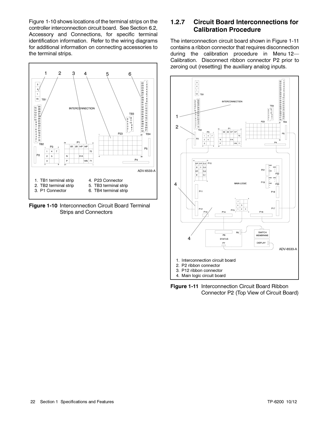
Figure 1-10 shows locations of the terminal strips on the controller interconnection circuit board. See Section 6.2, Accessory and Connections, for specific terminal identification information. Refer to the wiring diagrams for additional information on connecting accessories to the terminal strips.
| 1 | 2 | 3 | 4 | 5 | 6 |
|
|
|
|
|
| |
1. | TB1 terminal strip | 4. | P23 Connector |
| ||
2. | TB2 terminal strip | 5. | TB3 terminal strip |
| ||
3. | P1 Connector |
| 6. | TB4 terminal strip |
| |
Figure 1-10 Interconnection Circuit Board Terminal Strips and Connectors
1.2.7Circuit Board Interconnections for Calibration Procedure
The interconnection circuit board shown in Figure
1 |
|
2 |
|
4 |
|
| 4 |
| |
1. | Interconnection circuit board |
2. | P2 ribbon connector |
3. | P12 ribbon connector |
4. | Main logic circuit board |
Figure 1-11 Interconnection Circuit Board Ribbon Connector P2 (Top View of Circuit Board)
22 Section 1 Specifications and Features |
|
