2.6.1PC Communications
There are four ways to communicate between a PC and the generator set and/or transfer switch devices using KBUS communication protocol. The PC connections require optional software and possibly other hardware, communication modules in the generator set controller and/or transfer switch. See the monitor software operation manual for details. Contact your authorized distributor/dealer for availability.
Local Single Connection
A PC connects to the COM port of the controller module using an
| Generator Set |
| Controller, |
| Transfer Switch |
| Control, or |
| Power Monitor |
| |
Personal | up to |
Computer | 15 m (50 ft.) |
Figure 2-10 Local Single Connection, up to 15 m (50 ft.)
|
| Generator Set |
| Controller, | |
| Transfer Switch | |
| port converter | |
| Control, or | |
|
| |
| Power Monitor | |
|
| |
Personal | up to |
|
1220 m |
| |
Computer |
| |
(4000 ft.) |
| |
|
|
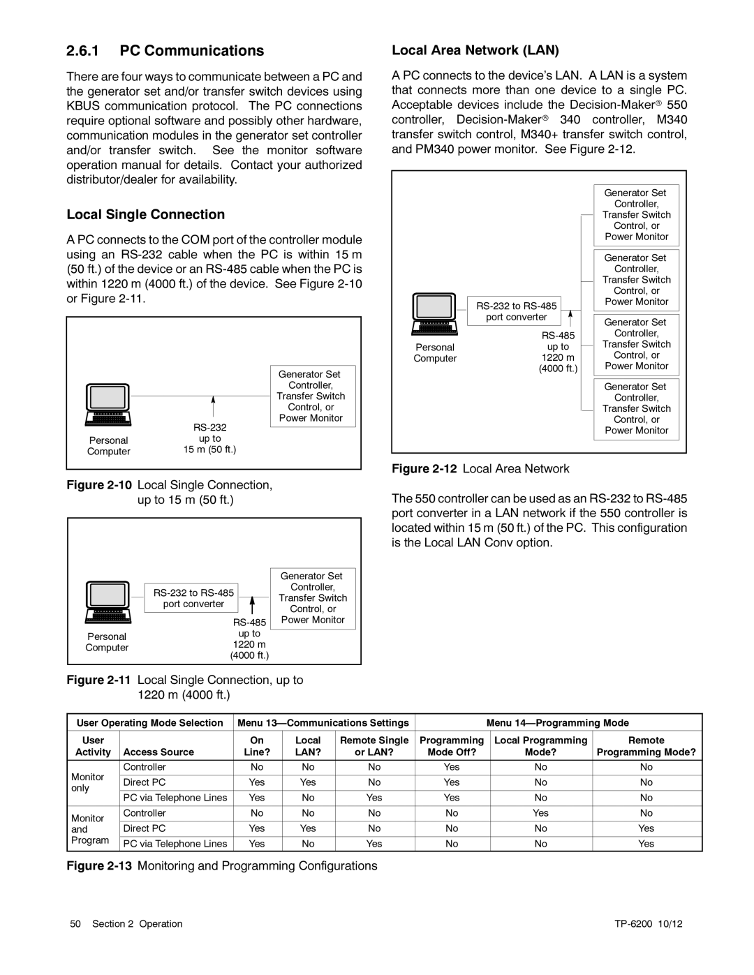
Local Area Network (LAN)
A PC connects to the device’s LAN. A LAN is a system that connects more than one device to a single PC. Acceptable devices include the
|
| Generator Set |
|
| Controller, |
|
| Transfer Switch |
|
| Control, or |
|
| Power Monitor |
|
| Generator Set |
|
| Controller, |
|
| Transfer Switch |
|
| Control, or |
| Power Monitor | |
|
| |
| port converter | Generator Set |
|
| |
| Controller, | |
Personal | up to | Transfer Switch |
Computer | 1220 m | Control, or |
| (4000 ft.) | Power Monitor |
|
| Generator Set |
|
| Controller, |
|
| Transfer Switch |
|
| Control, or |
|
| Power Monitor |
Figure |
| |
The 550 controller can be used as an RS-232 to RS-485 port converter in a LAN network if the 550 controller is located within 15 m (50 ft.) of the PC. This configuration is the Local LAN Conv option.
Figure 2-11 Local Single Connection, up to
1220 m (4000 ft.)
User Operating Mode Selection | Menu |
| Menu | |||||
|
|
|
|
|
|
|
|
|
User |
| On | Local | Remote Single | Programming |
| Local Programming | Remote |
Activity | Access Source | Line? | LAN? | or LAN? | Mode Off? |
| Mode? | Programming Mode? |
|
|
|
|
|
|
|
|
|
| Controller | No | No | No | Yes |
| No | No |
Monitor |
|
|
|
|
|
|
|
|
Direct PC | Yes | Yes | No | Yes |
| No | No | |
only |
| |||||||
|
|
|
|
|
|
|
| |
PC via Telephone Lines | Yes | No | Yes | Yes |
| No | No | |
|
| |||||||
|
|
|
|
|
|
|
|
|
Monitor | Controller | No | No | No | No |
| Yes | No |
|
|
|
|
|
|
|
| |
and | Direct PC | Yes | Yes | No | No |
| No | Yes |
Program |
|
|
|
|
|
|
|
|
PC via Telephone Lines | Yes | No | Yes | No |
| No | Yes | |
|
| |||||||
Figure 2-13 Monitoring and Programming Configurations
50 Section 2 Operation |
|