1.2.4Controller Circuit Boards
The controller has five circuit
12
5 | 4 | 3 |
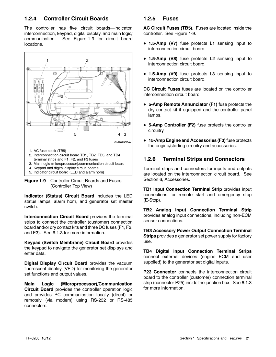
1.AC fuse block (TB5)
2.Interconnection circuit board TB1, TB2, TB3, and TB4 terminal strips and F1, F2, and F3 fuses
3.Main logic (microprocessor)/communication circuit board
4.Keypad and digital display circuit boards
5.Indicator circuit board (LED and alarm horn)
Figure 1-9 Controller Circuit Boards and Fuses
(Controller Top View)
Indicator (Status) Circuit Board includes the LED status lamps, alarm horn, and generator set master switch.
Interconnection Circuit Board provides the terminal strips to connect the controller (customer) connection board and/or dry contact kits and three DC fuses (F1, F2, and F3). See 6.1.3 for more information.
Keypad (Switch Membrane) Circuit Board provides the keypad to navigate the generator set displays and enter data.
Digital Display Circuit Board provides the vacuum fluorescent display (VFD) for monitoring the generator set functions and output values.
Main Logic (Microprocessor)/Communication Circuit Board provides the controller operation logic and provides PC communication locally (direct) or remotely (via modem) using RS-232 or RS-485 connectors.
1.2.5Fuses
AC Circuit Fuses (TB5). Fuses are located inside the controller. See Figure
D
D
D
DC Circuit Fuses fuses are located on the controller interconnection circuit board.
D
D
D
1.2.6Terminal Strips and Connectors
Terminal strips and connectors for inputs and outputs are located on the interconnection circuit board. See Section 6, Accessories.
TB1 Input Connection Terminal Strip provides input connections for remote start and emergency stop
TB2 Analog Input Connection Terminal Strip provides analog input connections, including
TB3 Accessory Power Output Connection Terminal Strips provides a generator set power supply for factory use.
TB4 Digital Input Connection Terminal Strips connect external devices (engine ECM and user supplied) to the generator set digital inputs.
P23 Connector connects the interconnection circuit board to the controller (customer) connection terminal strip (connector P25) inside the junction box. See 6.1.3 for more information.
Section 1 Specifications and Features 21 |